What is a breadboard
What is a breadboard
Breadboard – What, Why and How?
Breadboard is an essential tool for every electronics engineer and maker. In this blog post we’ll talk about why we use breadboards and how they work.
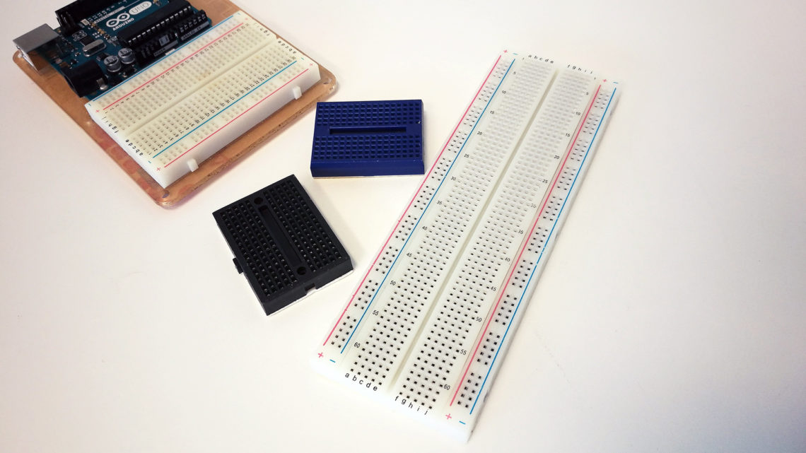
A breadboard is a simple tool which is used to easily connect electrical components and wires together. Only certain component types and wires is applicable for breadboard usage. As long as the components have through-hole pins (as opposed to surface mount), they are probably applicable for breadboards.
Components and wires are attached to the breadboard by simply pressing the pins down into the holes of the breadboard.
Electronic products almost always have PCBs (printed circuit boards) on the inside. These need to be designed, manufactured and soldered, which isn’t exactly done in a jiffy. Sometimes you need to hook up some electrical components for your prototype when you either don’t have time, interest or knowledge to acquire a PCB. If you just want test a potentiometer, you probably wouldn’t produce a PCB for that sole purpose.
In these cases the breadboard might be the perfect solution. With breadboards you can quickly connect simple electronic circuits and test them out.
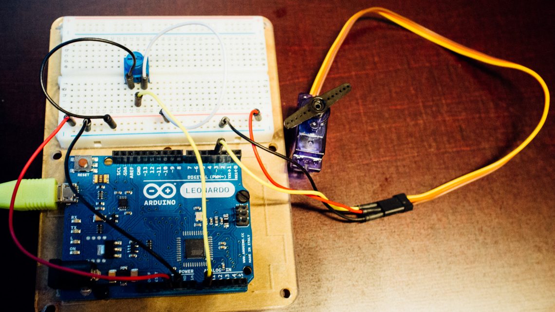
Breadboards are however not suitable as permanent circuits inside products and installations. In those instances a more “soldery” and failure-safe solution should be used.
To use a breadboard you just push the pins on either electrical through-hole components or jumper wires into the holes. The holes have springs in them to keep the components from falling out. The trick, however, is to put the pins into the right holes such that you get the circuit you want.
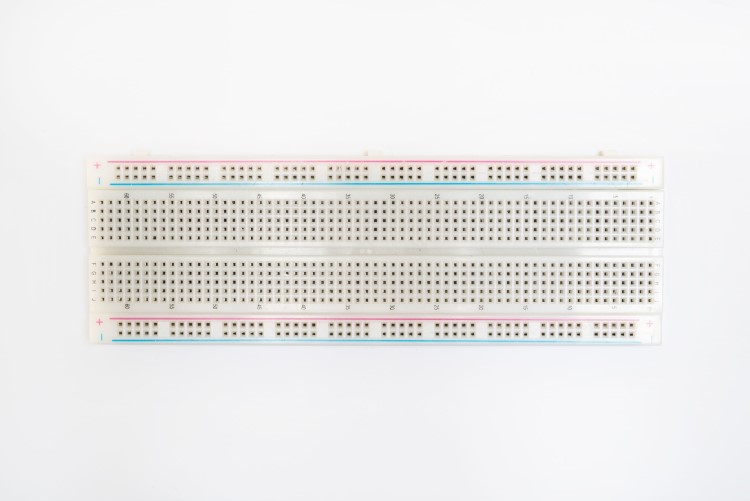
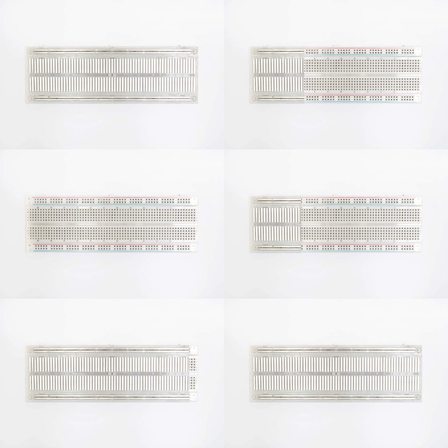
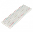
Some of the holes in breadboards are connected together and it’s important to know which. In the image below you can see how this is typically done.
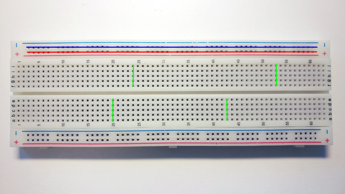
The red and blue holes are typically used as Vcc (e.g. +5V) and GND, respectively. Since many components often need connection to both of these lines, one can easily hook up to this “rail” wherever you want. The cravas along the center of breadboards like the one in the image above separates the connectivity between the green holes in the center.
If you’re unsure of how the holes in your breadboard is connected together, check it by using a digital multimeter.
Alternatives to Breadboards
There are a few alternatives to breadboards which require soldering. Two of them are veroboards and protoboards.
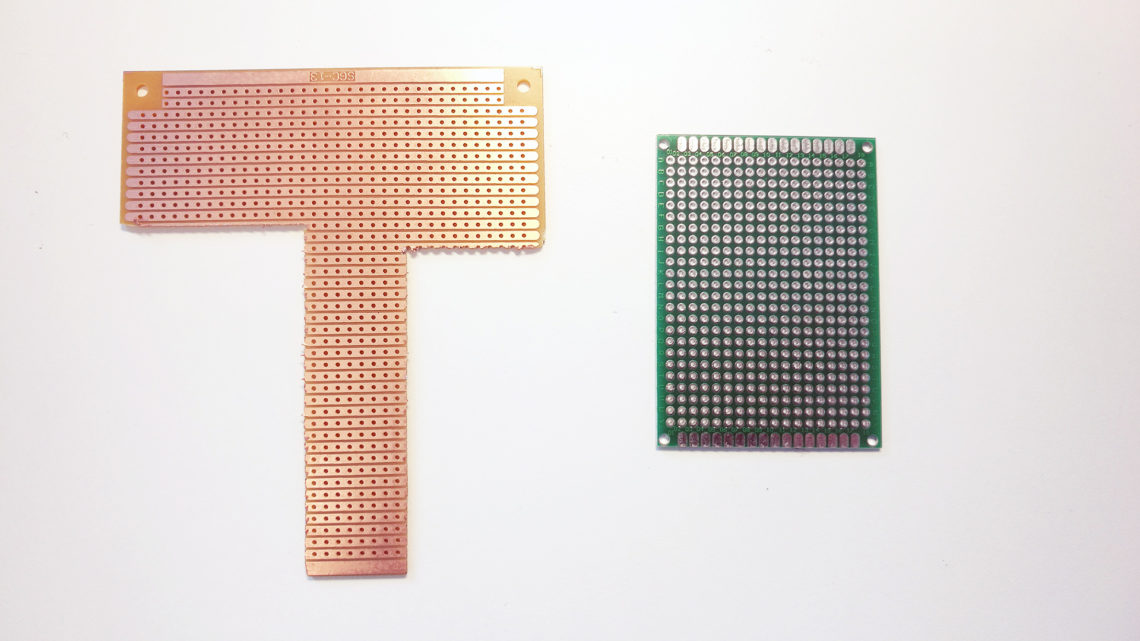
The most similar to breadboard is the veroboard. This board consists of a matrix of holes that are connected together along a single axis. The protoboards have the same type of holes except that none of the holes are connected.
Concluding Words
Breadboards are very nice for what they do, but isn’t useful in every scenario.
We might revisit the breadboard topic in the future to check how much current it can handle and other fun stuff, so (as always) stay tuned!
What is a Breadboard : Construction & Its Working
In the initial days of electronics manufacturing, engineers and designers have realized that sometimes designing a temporary circuit needs without soldering the components. So, an engineer took cardboard and arranged several rows into it to place nails. As per the circuit diagram, they placed components and nailed them through short wire pieces. The electrical connection can be provided by wrapping wire or soldering around the nails, and then components could be soldered to the wires. But by using cardboard, some resistive features may cause power loss. So, to overcome this process, at present breadboards were implemented by the scientists. Breadboards are one of the most essential rectangular pieces, used to build different circuits without soldering. This article discusses an overview of what is a breadboard, working, types and applications.
What is a Breadboard?
As the name suggests, the term breadboard can be derived from two terms namely bread & board. Initially, this was used to cut the bread into pieces. Further, it was called a breadboard & it was used in electronics projects and electronic devices in the year 1970. A breadboard is also known as a solderless board because the component used on the breadboard does not need any soldering to connect to the board, so it can be reused.
The arrangement of different components on a breadboard can be done by inserting their terminals into the breadboard, so it is frequently known as a plugboard. Breadboard definition is a plastic board in rectangular shape that includes a lot of small holes in it to allow you to place different components to build an electronic circuit is known as a breadboard. The connection on the breadboard is not permanent but they can be connected without soldering the components.
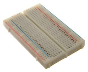
If you make any mistake while connecting the components, you can place or remove the components effortlessly. For beginners of electronics, this device is very helpful to make mini-projects. If a designer builds a simple circuit that they desire to analyze, then a breadboard gives a quick solution. The breadboard diagram is shown below.
The material used to make the breadboard is white plastic. At present, most of the breadboards are solderless types, so we can directly plug in the components directly and connected them through the exterior power supply. The different kinds of breadboards are accessible according to the specific point holes. For instance 400 point type, 830 point type, etc.
Specifications & Features
The specifications & features of a breadboard, include the following.
Types of Breadboard
Breadboards are classified into two types like a solderless breadboard and a solder-able breadboard.
Solderless Breadboards
This is the most commonly used breadboard for prototyping as well as testing electronic circuits without soldering the components. These are available in different shapes, sizes as well as ratings.
The circuits on these breadboards are not permanent so we can check & test the functionality of a circuit before confirming its design onto a PCB. These breadboards include rows & columns with holes that allow the leads of components & wire gauges.
If the terminal of the component does not place into the hole of a breadboard, then a connecting wire can be soldered to the lead of a component that will insert in the breadboard hole.
Advantages
The advantages of solderless breadboards include the following.
Disadvantages
The disadvantages of solderless breadboards include the following.
Solderable Breadboards
These types of breadboards offer a permanent setup for your electronic circuits. This kind of breadboard gives a stronger setup. It includes holes for electronic components including copper tracing. These components can be soldered using soldering iron for soldering the components to the breadboard so that an electrical connection can be formed through the copper tracing.
For designing a circuit, jumper wires are needed for soldering separately in between these components to make a lane to permit the flow of current. These types of breadboards are available in different sizes based on the requirement.
Advantages
The advantages of solderable breadboards include the following.
Disadvantages
The disadvantages of solderable breadboards include the following.
Selecting the breadboard from these two types will depend on the requirement as well as application. We have already discussed the pros and cons of these types of breadboards, so you can select accordingly
A solderless breadboard is suitable when you want to check a circuit without soldering the components. Similarly, if you want to check your circuit below some conditions that involve several movements similar to a robot then a solderable breadboard is the best option.
Breadboard Connections/Layout
Breadboards include several holes which are called tiny sockets. The arrangement of these can be done on a 0.1 grid. Most of the terminals of components can be placed directly into the holes on the board. Integrated circuits (ICs) are arranged across the middle gap through their dot or notch to the left. The designing of wire links can be done using a wire coated with plastic and single-core and the diameter of the wire is 0.6mm. Here, each connection on the breadboard is discussed below.
Different electronic components are compatible with breadboards like resistors, capacitors, switches, diodes, etc. These components which include lengthy metal legs are known as leads whereas components that include shorter metal legs are known as pins. All the electronic components including different sizes of leads will function through a breadboard.
Breadboards are mainly designed with holes to insert the components in the holes tightly, so they cannot fall out but they can drag them to detach them. The appearance of a breadboard includes rows, column, numbers, letters, blue & red lines
Letters
Letters on the breadboard are printed at the top & bottom that ranges from A to J that runs horizontally & the holes can be divided consistently into vertical lines.
Numbers
The horizontal rows can be identified through 1 to 30 numbers which are printed on the right and left edges on half-size breadboards, whereas in full-size boards 60 or 63 numbers are printed. Both the numbers & letters together will direct you to place a specific hole simply while designing complicated circuits.
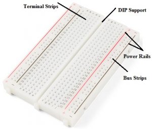
Terminal Strips
In the breadboard connection, the metal rows include small clips under the holes of a breadboard. The arrangement of every socket and metal strip can be spaced through a typical pitch with 2.54mm. These clips give support to connecting wires as well as leads of components to stick into the breadboard holes.
When any component is placed on a breadboard then the power supply can also be provided to any hole in that row because these are conductive & permits the flow of current from any end in that strip. Each strip in the breadboard includes five clips so we can connect simply five components within one specific section in the breadboard.
The row in the breadboard includes ten holes where each row can be separated through a crevasse or ravine in the center of the breadboard. This ravine separates both sides of rows & they are not connected electrically.
Power Rails
In the breadboard, there are horizontal and vertical rows, where the horizontal rows can be known as power rails and vertical rows are known as terminals. These are mainly useful in connecting the power supply toward the breadboard.
On this board, the red lines are positive rails whereas the blue lines are the negative rails. Usually, breadboards have different connections like power rails which are known as metal strips.
It is significant to be alert that the power rails on each side are not connected, thus if you want a similar power source on two sides, then you have to connect the two faces through some jumper wires.
Rows and Columns
In breadboards, we can notice that rows and columns are marked through letters. These are very helpful while designing a circuit on the board. If the component on this board is misplaced by mistake then the circuit can get quickly complicated otherwise it will not work at all. If you identify the row number in the breadboard for the connection then it is very easy to place the component into the board.
On the breadboard, the connection of the circuit doesn’t have to be in the correct location as shown in the circuit. Actually, it doesn’t even have to look similar. If all the circuit connections are being completed, you can design your circuit in your way.
Terminal Strips
Terminal strips in breadboards occupy most of the place. These are made up of small holes, where you can insert your components. The connection of these strips can be done in a specific way depending on their columns & rows. It is essential to recognize the terminal strip layout on the breadboard. Check the breadboard labeling before inserting components.
Metal Clips
In every breadboard, metal clips will hold an electronic component once it gets plugged in. The arrangement of these clips can be done in lines that respond to the rows as well as columns on the terminal strips of the breadboard. So that you can notice & control which components are inserted on the board
Binding Posts
Some kinds of breadboards are designed on a stand that includes binding posts by attaching to it. These posts permit you to attach all types of power sources to your board. In some types of breadboards, binding posts are used to connect exterior power sources. The primary step to use these posts is to attach them to the board through some jumper wires.
By using these posts, we can simply connect wires toward the posts to attach them to the board. Usually, you have to attach a power as well as the ground wire from the posts toward the breadboard. If you require any additional power source, then you can utilize the alternate post. Once the posts are connected to the breadboard, then you can use several methods to fix the power supply toward the posts as well as toward the breadboard.
Benchtop Power Supplies
Benchtop power supplies mainly used in electronics labs which provide an extensive range of current & voltage to your circuit. A banana connector is used to give a power supply toward the binding posts. The power supply to a breadboard can be supplied with binding posts using banana cables.
On the other hand, you can use IC hooks, alligator clips otherwise any other cables through a banana connection to hook your board up to various supplies. Another advanced technique of utilizing the binding posts is to connect a barrel jack with wires & attach them to the posts but it needs some middle soldering skills.
Connection of ICs on Breadboard (DIP Support)
Generally, connecting electronic components on a breadboard like resistors, capacitors, diodes, etc is quite easy but connecting integrated circuits (ICs) is quite different. When we notice the board, there is a gap line within the two vertical columns. This gap is very helpful in connecting ICs on a breadboard.
We can place any size of integrated circuits onto the breadboard through break rail without shorting its terminals. You can notice the connection of IC in the following image, which includes five holes within a single column. Once an IC is placed then we can have four available holes for each pin of an IC to make interconnection. We can place a wire at any place from these 4 points to acquire a connection through that specific IC pin.
Breadboard Wires
There are different types of wires are used for breadboards based on the requirement. So selection of wires is essential for breadboards to build the projects, so instead of standard wires, different types of wires are used which include the following.
Jumper Wires
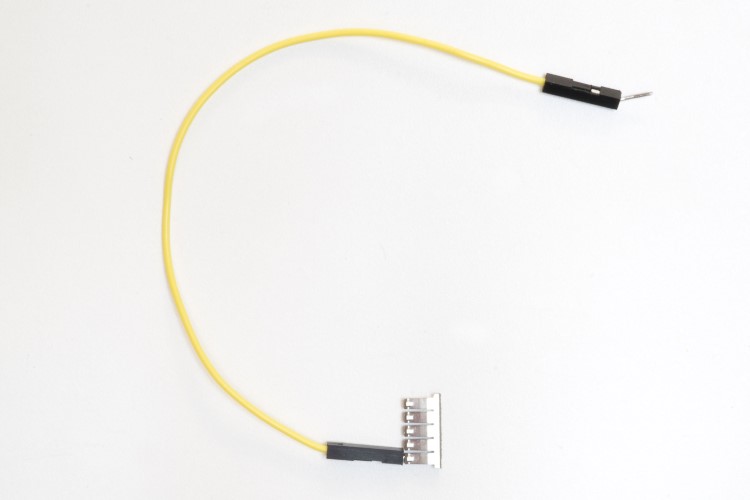
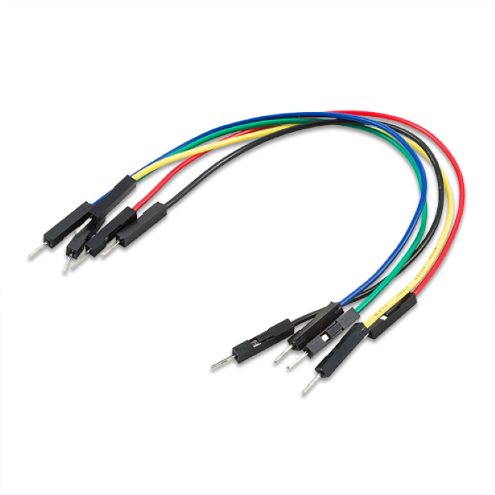
Jumper wires are used in making small circuits as they are slightly longer. These wires are harder to track the errors. Jumper wires metal pins connected to the end and are flexible, so it will be simple to insert into the board. In electronics stores, these wires are easily available but at little cost.
Jumper Wire Kit
The jumper wire kit is one kind of plastic box including wires in different sizes, lengths, and colors. Both the ends of these wires are twisted at 90 degrees so that it will be very easy to insert into the breadboard. As compared to lengthy wires, these wires are very perfect & neater Jumper wires are available with two or more links in several colors, make it difficult to arrange the circuit with standard color code.
Hookup Wires
These wires are also called lead wires which are available in rolls and insulated with single-core. The length and the insulation of this wire can be removed through some tools namely wire strippers to use as a jumper wire. These kinds of wires are available in various colors and at less cost. So we can easily color-code the circuit.
Before choosing these wires, one thing we have to keep in mind that is, you have to purchase solid single core type wire instead of standard wire. Because solid core type wires are designed with a single solid metal part because these are very rigid. So inserting it into the breadboard is very simple. Whereas, standard wires are designed with several separate wires but these wires are very solid to insert into the breadboard
Alternatives
The alternatives of breadboards which need soldering are veroboards & protoboards. The most similar type of board is the Veroboard which includes holes that are connected through a single axis. Another alternative is protoboards which include similar kinds of holes but none of the holes on the board are connected.
Advantages
The advantages of breadboard include the following.
Disadvantages
The limitations or disadvantages of breadboards include the following.
Uses/Applications
The applications or uses of a breadboard include the following.
Different Ways to Power a Breadboard
There are different methods to providing power supply to a breadboard like using Arduino Board, Battery & a Dedicated Power Supply.
Using Arduino Board
If you are an Arduino user, then this technique is very simple for you because, the Arduino board gets its power supply from an exterior power supply or a computer, so you can just give power to a board by borrowing its power supply. To protect the board from the Arduino, you need to follow these steps
Using a Battery
How to Use a Breadboard?
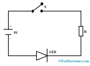
Here is a simple example circuit to know how to use a breadboard. First, we need to connect a simple circuit to the breadboard. Previously, we have discussed the board, connections, and it’s working but now we have to start connecting a circuit on a breadboard. Here, a simple LED circuit is taken to give connections on the board. This circuit can be built with a resistor, LED, and power supply. To make a circuit with an LED, the following steps we have to know.
Basic LED Circuit Diagram
Step-1
Place the LED into the Breadboard by bending the long terminal of the LED. Plug the anode terminal of the LED into the top rail on the breadboard whereas the short terminal is inserted into the main part
Step-2
Place the resistor on the breadboard & bend the resistor terminals to plug one of the terminals of a resistor into a hole under the cathode terminal of the diode.
Step-3
Place the connecting wire into the Breadboard under the resistor terminal & the bottom rail.
Step-4
Connect the two terminals of the battery to the Breadboard. In this board, the battery’s red wire can be connected to the top rail whereas the black wire can be connected to the bottom rail. Switch on the battery to provide the power supply to the circuit so that the LED will turn ON.
Circuit Connection on Breadboard
Common Mistakes
A common mistake while connecting a circuit on a breadboard is not very important because connections of the board are temporary. So, you can simply reconnect the circuit by changing the components. However, you have to pay attention to some common faults & keep away from them to complete your project easily. The common mistakes are
Safety Tips for Breadboard
It is very important to connect a circuit systematically & neatly on a breadboard so that one can correct it & get it running simply & rapidly. It also assists once someone else requires knowing and inspecting the circuit. The following tips are very useful for breadboard.
Breadboard Sizes
There are different sizes of breadboards are available in the market which is used based on the application.
Half Size
The half-size breadboard is applicable for mini-projects. The length and width of this board is 5.5 cm x 8.5 cm including a standard dual strip within the middle & two power rails on two faces. In this breadboard, power rails can be removed simply to make the board thin.
Tiny Breadboard
These breadboards are very small in size. This kind of breadboard does not include power rails however it includes 17 rows. These boards are applicable when you have fewer components to connect.
Little Breadboard Bits
These breadboards are available in different sizes like 4X4, 2X8, and 2X4. The 4×4 type includes hour strips with four-pin terminal strips. The 2×8 type includes 8 strips with two-pin terminal strips. The 2×4 boards include 4 strips with two-pin terminal strips.
Large Breadboards
Large breadboards are big in size, very useful for major projects which are located onto a metal plate. These boards are available with four colored posts which can be used through a bench-top supply. These boards include bumpers to maintain the board from slipping in the region of your desk.
How to Choose a Breadboard?
There are several factor need to consider while choosing a breadboard. The following factors need to consider once purchasing a breadboard.
Thus, this is all about an overview of a breadboard, connections, how to use, different wires used, types of boards, advantages, disadvantages, and its uses. From the above information, finally, we can conclude that it is used to connect and test the circuits. Breadboards are essential to building different circuits as well as electronics projects. A breadboard allows you to test your own mini-project circuits, however, it also includes the correct category to assist you to follow a board diagram.
The connection of a circuit can be done by inserting different components through holes on the breadboard. The main benefits of using a breadboard are that the electronic components are not soldered. If the components are placed incorrectly then they can be moved simply to the latest location on the board. Here is a question for you, what is a Printed Circuit Board or PCB?
How to Use a Breadboard [with Q&A]
What exactly is a breadboard
A breadboard is a rectangular board with many mounting holes. They are used for creating electrical connections between electronic components and single board computers or microcontrollers such as Arduino and Raspberry Pi. The connections aren’t permanent and they can be removed and placed again. In fact, you can even replace components to customize your project or work on a completely different one, using the same breadboard.
The vertical columns of the breadboard are called terminals, while the horizontal long rows are called power rails because they are mostly used to connect the power supply to the breadboard. The positive rails are indicated by red lines, while the negative rails are indicated by black ones.
Breadboards are used to help you connect components to complete your basic circuit. The reason it’s called breadboard dates back to when electronics components were much bigger and people would actually use wooden breadboards (boards used to cut bread) to connect electronic circuits. Fortunately, things have changed since then and only the name has been retained.
Breadboards are sold separately by most electronics distributors, and they also appear in most of the basic electronics kits you’ll buy.
Breadboard connections
A breadboard connection with an electronic component is made with the help of leg-like structures made of metal. These are called “leads”, and they can vary in size. The shorter ones are often referred to as pins. So, if your electronic component has leads, it can be connected directly to the breadboard. DIP-based (that’s dual inline package) integrated circuits are built to fit perfectly into a breadboard, with each pin fitting over a breadboard hole.
These leads can be pushed into the holes that are designed to hold them in place and prevent them from getting loose or falling out of the breadboard. You can even turn the breadboard upside down and these connections wouldn’t come off. They are tight enough to insert and remove, but, not enough for breadboard connections to come off on their own.
The tightness comes from the fact that breadboards have small metal clips hidden under these holes, which hold everything in place. They basically grab onto the leads that you insert. Other than that, breadboards usually have a backing layer as well, to hold the clips themselves in place. This backing layer is normally made of a double-sided tape. One side of the tape is usually covered to prevent the sticky layer from being exposed.
However, if the breadboard needs to be attached to your electronic project, you can peel this cover off and use the other sticky side. The next thing you’ll notice on a breadboard are the markings such as letters, numbers, and symbols. The way these markings are laid out may vary from breadboard to breadboard. But, the purpose is all the same. These markings help users locate the exact holes they need to connect the components to. The closest example of this would be an Excel spreadsheet. You have cells, rows, and columns. The row number and the respective column letter tell you which cell you need to be looking at. It’s almost the same with breadboards.
For example, C12 refers to the breadboard hole under column C and in row 12.
Breadboard power supply
There are plenty of ways to supply power to a breadboard. For starters, you can always borrow power from development boards such as Arduino or Raspberry Pi. Arduino boards come with female headers from which power can be sourced. You have a range of pins for ground and power that can be connected to a breadboard’s power rows. The Arduino board itself receives power from an external power source that is connected to the circuit. This could be a battery or even a wall unit.
Apart from that, you have binding posts on certain breadboards. These posts first need to be connected to the board using jumper cables and then, you connect wires to the binding posts. Other than that, you have breadboard power supply options such as benchtop power supply and special power supply units built exclusively for breadboards. These units usually come as part of a breadboard kit. Some of them let you draw power directly from a wall unit or through your computer via the USB port.
One of the commonly used breadboard power supply modules is a circuit board that is connected to the top of a breadboard. This module provides power via the breadboard’s power rails. These modules can be either in 3.3 V or 5 V fixed dual output regulated configurations. There are a few that come with variable power supplies as well. This can be helpful if you need over 5 V.
How to use a breadboard
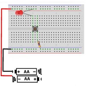
Now that you have a basic idea of a breadboard, the next step is to actually learn how to use it. The way breadboards are used can vary based on the specific project you are working on. So, to give you a practical example of how a breadboard works, we’re going to us a minor circuit as an example. For this circuit, we will be using a LED, AA or AAA battery pack with black and red leads, a push button, a 100ohm resistor, and, of course, a breadboard. You will use these components, including the breadboard, to create a working electronic circuit. The first step is to connect the red lead in the battery pack to the breadboard’s power bus. Then, you connect the black lead to the ground bus. The third step is to connect the resistor from B12 to the ground bus.
As for the push button, the four pins need to go into holes E10, F10, E12, and F12, respectively. Finally, the LED’s short lead into the J10 hole and the long LED into the power bus. Your basic LED circuit is now ready. You can use this diagram to get a clear idea of how to create the circuit. You can also refer to this image. Of course, you don’t have to follow the diagram exactly as it is. You can make changes as long the circuit is “electrically equivalent”. What that means is the electricity has to flow through a closed circuit, which is what will allow it to function as intended.
Types of breadboards
Today’s breadboards are made from all sorts of materials and they vary in size and shape as well. Larger breadboards are great for prototyping complex projects; mini breadboards are suited to smaller ones.
However, if you were to divide breadboards into broader categories, you would end up with two key types of breadboards – solderless and soldered. Solderless breadboards are what we have been discussing so far and they are the best option, especially when you’re a beginner. They are called “solderless” because there is no soldering required to create connections or to hold things in place. For those who are wondering what soldering is- it’s a method of connecting electronic components together by melting a metal known as solder. The melted solder conducts electricity, which helps create the circuit and it fuses with the connected ends to hold the connection together.
Which brings us to the topic of soldered breadboards. These are breadboards where the connections are soldered. There are no metal clips to hold the leads. Soldered breadboards are rarely used. In fact, soldering is mostly done on PCBs or Printed Circuit Boards. Before that happens, engineers or technicians will actually use a solderless breadboard for prototyping. They move onto a soldered PCB only if the prototype is a success. So, these are the two main breadboards you are likely to come across.
Breadboards and circuito.io
Hopefully, you’ve developed a rough idea of what a breadboard is and that’s great. But you probably have a few questions still hovering around in your head, for example, what are the applications of breadboards in circuito.io?
So, we’ve created a list of FAQs that we normally receive from our users. The answers to these FAQs will hopefully make it much easier for you to use a breadboard in conjunction with the projects on circuito.io.
Q: Does it matter which color jumper wires I use on my breadboard?
The simple answer to this question is «no». Jumper wires are all the same. However, for the sake of avoiding confusion, it is recommended that you use one set of the same color wires for “+” connections and one set of another color for “-“ connections.
In fact, it’s even better if you use red wires for “+” connections and blue or black for “-“connections.
Q: Is it important to use a specific breadboard hole when making connections?
Again, no. The hole doesn’t matter as long as you are using one that’s on the same power rail or terminal strip. This is because the power rails are linked to each other and so are the terminal strips. So, the current flow and the conductivity are maintained within a specific strip.
However, if you were to skip to another terminal strip or power rail, then you would see a problem with your connection.
Q: Are the “-“ and “+” power rails different from other terminal strips or rows?
No. The horizontal rails function in much the same way. They are all connected and used to connect the positives and the negatives. However, do note that the power rails on both sides of the breadboard aren’t connected. So, if you have to use both those power rails, you have to make sure both of them are connected to the main breadboard power supply (and therefore to one another).
Q: Can two jumper wires be connected to the same socket?
No. This isn’t possible. However, in some replies from circuito.io you may see two jumper wires being connected to the same hole. If you come across such diagrams, don’t worry. The solution is quite simple: all you have to do is connect the wires to different holes within the same row.
Q: What should I do when there isn’t enough space on my breadboard for all the components?
This isn’t a problem to worry about. You can always use a bigger breadboard or two breadboards together. In fact, most modern breadboards come with notches or tabs that allow you to connect another breadboard. You can actually use multiple breadboards this way, using a pair of red and black jumper wires to connect the positive and negative rails.
From prototype to product
As we mentioned earlier, breadboards are used to create prototype circuits. Once you test a prototype and it proves to be successful, the next step is to go ahead with creating a PCB (Printed Circuit Board). Breadboards are temporary and they will always be subject to disconnection, which isn’t helpful if you’re going to construct a device that needs the connections to remain undisturbed. This is where PCBs come in handy. The connections in a PCB are soldered and therefore permanent. Breadboards are used mainly as a planning tool before manufacturing PCBs. They allow you to test the basic layout of your electronic circuit and tell you where a certain component needs to be placed and how it needs to be connected.
You can use Fritzing Fab to do this. Fritzing Fab is an online tool that allows you to create actual PCBs based on your fritzing sketches. PCBs are quite complex and the kind of people who work on them are usually electricians and other experienced individuals who have been working on circuits for a long time. One of the most popular tools used to design PCBs is Eagle. You can access more tools via our about online tools for makers and scroll to the PCB Design section. There is also this article for additional help.
Running Breadboard
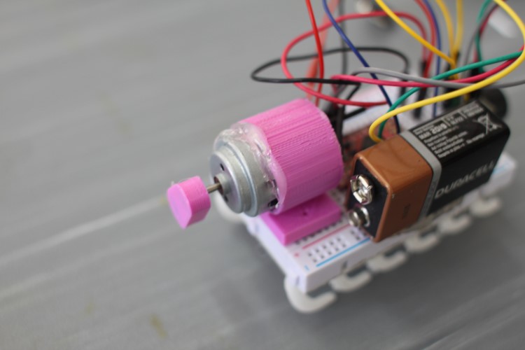
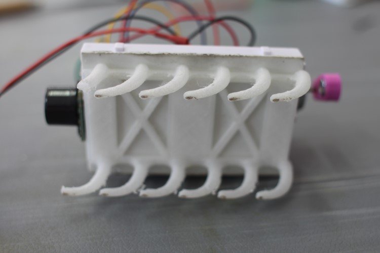
The running breadboard is a simple project we made that uses a breadboard as an integral part of the design. The components for this build can be found on our Hackster Project Hub.
The final circuit is then arranged and connected to the breadboard using the remaining components. To get a good idea of what the circuit should look like, click this link.
Another thing to remember here is that you can to test your circuit using test code. The test code can be accessed by clicking the previously provided circuito.io link. Clicking this link will take you to a page where the circuito.io tool shows you how the circuit needs to be generated. Below, you will notice a button that says “Generate”. Click that button. Once you do that, you will be lead to a “step-by-step” guide. This guide provides each and every step that goes into setting up the circuit in detail. Towards the end, you will notice a section that says “code”. This is where you can download the test code.
Once you download the test code, upload it to the Arduino boards and carry out the test. If all goes well, the next step is to use the modified code, which can be accessed here. And you made yourself a running breadboard!
We hope you found this guide helpful and you now have a better understanding of what breadboards are and how to use them. As we mentioned earlier, breadboards aren’t complex devices. They might be a bit confusing at first, but, they are far from complicated. All you need to do is learn about them and things become super easy after that.
We invite you to take the information in this guide and, get a basic electronics kit, and start building your own project since that’s the best way to learn (in our opinion of course). Take the time to get to know about breadboards by incorporating them into your electronic circuit projects. Or, look for projects that require extensive use of breadboards. Breadboards are an incredibly useful prototyping tool, and the more you use them, the more you’ll get from them!
How to Use a Breadboard
Introduction
Breadboards are one of the most fundamental pieces when learning how to build circuits. In this tutorial, you will learn a little bit about what breadboards are, why they are called breadboards, and how to use one. Once you are done you should have a basic understanding of how breadboards work and be able to build a basic circuit on a breadboard.
Looking for the Breaboard that’s right for you?
We’ve got you covered!
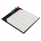
**Description**: This is your tried and true full size solderless breadboard! It has 2 split power buses, 10 columns, and 63 …
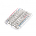
**Description**: Ever wonder what goes on inside these things? Well this clear bread board might enlighten. Beyond the cl…
**Description**: How could anyone improve on the clear plastic breadboard. I mean, that’s pretty sweet right? What if it wa…
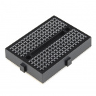
This black Mini Breadboard is a great way to prototype your small projects! With 170 tie points there’s just enough room to b…
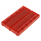
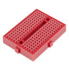
This red Mini Breadboard is a great way to prototype your small projects! With 170 tie points there’s just enough room to bui…
Suggested Reading
Here are some tutorials and concepts you may want to explore before learning about breadboards:
Connector Basics
What is a Circuit?
Voltage, Current, Resistance, and Ohm’s Law
Working with Wire
How to Read a Schematic
How to Use a Multimeter
History
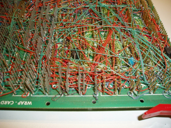
If you wanted to build a circuit prior to the 1960s, chances are you would have used a technique called wire-wrap. Wire wrap is a process that involves wrapping wires around conductive posts attached to a perfboard (a.k.a. a protoboard). As you can see, the process can get rather complex very quickly.Although this method is still used today, there is something that makes prototyping much easier, breadboards!
What’s in a Name?
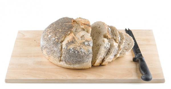
When you picture a breadboard in your head, you may envision a big piece of wood and a large loaf of freshly baked bread. You wouldn’t be too far off either.
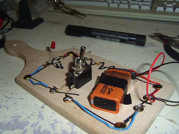
So why do we call this electronic “circuit builder” a breadboard? Many years ago, when electronics were big and bulky, people would grab their mom’s breadboard, a few nails or thumbtacks, and start connecting wires onto the board to give themselves a platform on which to build their circuits.
Since then, electronic components have gotten a lot smaller, and we’ve come up with better ways to connect circuits, making moms all over the world happy to have their breadboards back. However, we are stuck with the confusing name. Technically, these are still breadboards, but this discussion is going to be on modern, «solderless» breadboards.
Why Use Breadboards?
An electronics breadboard (as opposed to the type on which sandwiches are made) is actually referring to a solderless breadboard. These are great units for making temporary circuits and prototyping, and they require absolutely no soldering.
Prototyping is the process of testing out an idea by creating a preliminary model from which other forms are developed or copied, and it is one of the most common uses for breadboards. If you aren’t sure how a circuit will react under a given set of parameters, it’s best to build a prototype and test it out.
For those new to electronics and circuits, breadboards are often the best place to start. That is the real beauty of breadboards—they can house both the simplest circuit as well as very complex circuits. As you’ll see later in this tutorial, if your circuit outgrows its current breadboard, others can be be attached to accommodate circuits of all sizes and complexities.
Another common use of breadboards is testing out new parts, such as Integrated circuits (ICs). When you are trying to figure out how a part works and constantly rewiring things, you don’t want to have to solder your connections each time.
As mentioned, you don’t always want the circuit you build to be permanent. When trying to duplicate a customer’s problem, SparkFun’s Technical Support team will often use breadboards to build, test, and analyze the circuit. They can connect the parts the customer has, and once they’ve gotten the circuit setup and figured out the problem, they can take everything apart and put it aside for the next time they need to do some troubleshooting.
What is a Breadboard?
Published Feb 14, 2019
With all the powerful and fun to use development boards out there, there’s a lot you can do without a breadboard. However, if you’re setting up small circuits for learning the basics of electronics or need a place for peripheral components, breadboard is a great tool to have.
What is a Breadboard?
A Breadboard is simply a board for prototyping or building circuits on. It allows you to place components and connections on the board to make circuits without soldering. The holes in the breadboard take care of your connections by physically holding onto parts or wires where you put them and electrically connecting them inside the board. The ease of use and speed are great for learning and quick prototyping of simple circuits. More complex circuits and high frequency circuits are less suited to breadboarding. Breadboard circuits are also not ideal for long term use like circuits built on perfboard (protoboard) or PCB (printed circuit board), but they also don’t have the soldering (protoboard), or design and manufacturing costs (PCBs).
Why is it called a Breadboard?
In the before times, boards used in the kitchen for cutting bread were used by young circuit designers to build circuits on with screws or nails driven into the board with wires wrapped around them to complete circuits. This was an improvement on ‘deadbug’ or direct solder connections, since the circuit could be nailed down and secure as well as easily modified if necessary for debugging or enhancements. The name has stuck through to today, even though placing circuits on boards for bread is only done for Instagram posts.
Why do you use a BreadBoard?
As mentioned before, a breadboard is handy because you can set up circuits quickly and temporarily to test them and move on to a more permanent arrangement after investigating how it works on the breadboard. They are great for hobbyists and tinkerers to set up projects as a standalone device, or as a peripheral to an Arduino, Raspberry Pi, LaunchPad, BeagleBone, and many other development boards. They come in many sizes to fit projects large and small. Breadboards are also inexpensive, and the parts that work with them are also typically inexpensive too. If you want to make your project more permanent, moving from a design on a breadboard to protoboard or PCB will be easier than skipping to those harder to manipulate boards.
If you’re just getting started, or are well down the path of electronic design, you’ll run across breadboards. Getting to know their strengths of quick and easy circuit creation, and their weaknesses of impermanence and limitations in terms of power handling and RLC (resistance, inductance, capacitance) effects will help you create many fun and useful projects later.
Images Source:
Authored By
Gary Crowell
Avid biker, audio enthusiast, tinkerer, and radio/autonomous car racer. Also work with PCBs, electronic/mechanical design, and programming, so I really get interested if the project is mechatronic.
Explore CircuitBread
Related EE FAQs
How to transfer circuit from schematics to breadboard?
Answered by Gary Crowell
How much power and how high of a frequency can a breadboard handle?
Answered by Gary Crowell
What are the things to think about with the structure of breadboards?
Answered by Gary Crowell
How do I go from a Breadboard to a PCB?
Answered by Gary Crowell
Related Tutorials
Friends of CircuitBread
Check Out Our Free Ohm’s Law Calculator
Product Samples Upon Request
Get the latest tools and tutorials, fresh from the toaster.
