What is an electrical circuit
What is an electrical circuit
What is an Electronic Circuit?
by Santosh Das | Last Updated On July 4, 2021
Electronic Circuits for Beginners.
An Electronic Circuit a structure to direct and control electric currents perform some useful function.
The very name “circuit” implies that the structure is closed, something like a loop.
Table of Contents
What is Electric Current?
The name “current” refers to some type of flow, and in this case it is flow of electric charge, which is usually just called charge because electric charge is really the only kind there is.
What is an Electric Circuit?
An Electric Circuit is a conductive path for flow of current or electricity. It is also called electrical circuit. A conductive wire is used to establish relation among source of voltage and load. An ON / OFF switch and a fuse is also used in between the source and load.
When is a Circuit Called Electronic Circuit?
A circuit comprising of electronic components such as capacitor, resistor, diode, transistor, inductor, coil, transformer etc is called an Electronic Circuit. These components can be either through-hole or SMD.
These components or devices are connected to each other via conductive traces (generally of copper) or conductive wires through which electric current can flow. In simple words, these electronic components are soldered onto a PCB to perform a predefined work.
A circuit to be called “Electronic Circuit” rather than an “Electrical Circuit” must have at least one active component.
What are Active Electronic Components?
Active electronic components are those that can control flow of electricity. Most PCB (Printed Circuit Board) have at least one active component.
Example: Transistors, Integrated Circuits or ICs, Logic Gates, Vacuum Tubes, Silicon-Controlled Rectifiers (SCRs).
What are Passive Electronic Components?
Passive components are those that do not have gain or directionality. They are also called Electrical elements or electrical components.
Example: Resistors, Capacitors, Diodes, Inductors.
Types of Electronic Circuit
An circuit can of following types:
1. Analog Electronic Circuit
A Simple Analog Circuit
Analog electronic circuit are those in which signals may vary continuously with time to correspond to the information being represented.
Example: Electronic Equipment like voltage amplifiers, power amplifiers, tuning circuits, radios, and televisions are mainly analog.
2. Digital Circuit
A Simple Digital Circuit
A digital circuit is a circuit where the signal is either of the two discrete levels – ON / OFF or 0 / 1 or True / False. Transistors are used to create logic gates perform Boolean logic.
Example: Multiplexers, De-multiplexers, Encoders, Decoders, Counter, Flip-Flop
3. Mixed-Signal Circuit
A Mixed-Signal Circuit
Mixed-Signal Circuit, are also called hybrid circuits, contain elements and properties of both Analog Circuit and Digital Circuit.
Examples: Comparators, Timers, PLLs, ADCs (Analog-to-Cigital Converters), and DACs (Digital-to-Analog Converters).
Types of Electric Circuit
What is an electrical circuit
If we want to know better about electricity, want to fix an electrical device, or you are planning to be an electrician? You better know exactly “what is an electrical circuit”. In this post we will not only learn what an electrical circuit is, but everything is related to it. There are a lot of things we need to perfectly understand an electrical circuit.
At first we are going to learn electric circuit definition along with its electronic and electric circuit symbols. The types of electrical circuits are also crucial for us to analyze the circuit and avoid the risks and get better solutions. Here you will also understand the basic and common components of an electric circuit.
If you’re reading this right now, I bet you want to figure out ‘what exactly is electricity and electric circuits’. May it be your own curiosity, homework, paperwork, or even just study it for an upcoming test, you need to know what electricity is and electric circuits.
We know, the explanation itself is too wide and too narrow at the same time. You may find a lot of differences in its theory but at the same time, you may not find the answers you are looking for.
Well, electricity itself is like ‘magic’. You can’t see it with bare eyes but can feel its presence.
Well said, now you have found your best answer here. Here we will learn the basic things about: what is electricity actually, when was it invented, who discovered it, what is an electrical circuit and how it works, and last we will learn electric circuit types and the examples.
What is Electricity
Electricity is called physical phenomena related to the presence of matter which has the property of electric charge. Ages ago, electricity was considered not related to magnetism.
But after Maxwell’s demonstration, both magnetism and electricity are considered as a single phenomenon. The definition of electricity may be:
If you type ‘what is electricity’, the explanation above is the simple definition of electricity. What is our concern is the electric charge.
This matter can be either positive or negative and produces an electric field. Its movement is called by electric current and is able to produce a magnetic field.
When Was Electricity Invented?
Thomas Edison, an American inventor, did outstanding research, the light bulb in his laboratory in 1879. At the end of the 1880s, small electrical stations were built using Edison’s design in the city of the U.S.
Later after this research, we will know Alessandro Volta, The one who invented the electric circuit.
Alessandro Volta made the invention of the first electric circuit in 1800. He made the statement that connecting the bowls of salt solution with metal strips can produce a steady flow of electricity.
He used a disc of copper, a salt solution soaked cardboard and zinc. His voltaic pile is known as an early battery. By connecting a battery with single copper wire from top to bottom, an electric current flows.
Who Discovered Electricity?
Even electricity is one of the natural phenomena, the one who discovered it needs to be credited. Benjamin Franklin is the first one who discovered electricity with a simple experiment.
He was a passionate researcher and had his golden time on a scientific matter at that time. He had so many great discoveries.
After electrical energy is found by Benjamin Franklin, who is next? The next person is Alessandro Giuseppe Antonio Volta or Alessandro Volta for short.
He was an Italian physicist and the inventor of electricity and power. His most known invention for us is his electric battery.
The voltaic pile is his innovation in 1779-1880. From this invention, we can generate electricity using chemical processes.
What is an Electrical Circuit
When we hear about a circuit, the first thing we imagine is a loop. This loop is connected from head to tail just like a racing circuit. This is the basic idea of “circuitry definition”.
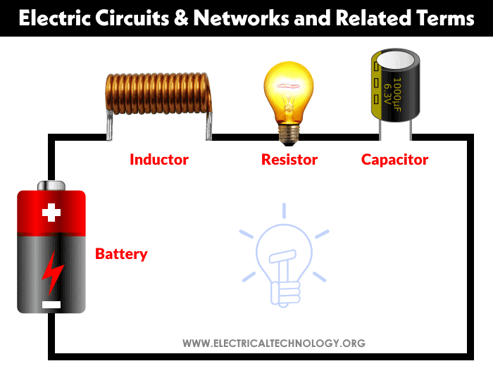
An electric circuit definition is a “circuit” or “path” for the electric current to flow. Not only the path, but an electrical circuit consists of a component which is able to give electrical energy to the circuit, a component which is able to convert the electrical energy to a different form of energy. For the energy supply, we can use a battery and generator.
The component or device that changes the energy to another form of energy can be an electric motor, lamp, heater, device such as a computer and charger, or many more. Don’t forget that we need the “path” or “circuit” which is a conductor, wire, and other transmission line.
An electric circuit is an interconnection of several electrical components so that the electric charge can flow along in a closed path or closed circuit.
This circuit can be used for various applications.
Electrical circuits contain active and passive electric elements such as resistors, inductors, capacitors, transformers, switches, and many more.
It is very important to learn the parts of electrical circuits, their symbols, and their functions.
If you try to search what is the definition of an electrical circuit, you will find a lot of explanations. But, they actually have the same meaning, just presented in different words. Don’t confuse yourself with such a basic explanation.
An electric circuit is an interconnection of electrical elements
Summary, you can call an electrical circuit as a path or transmission line where an electric current flows through. If the circuit is joined from the start to the end of the line, we call it ‘closed-loop’.
This circuit makes the electric currents able to flow. Otherwise, we call it an ‘open circuit’ where the circuit is not connected at both ends and the electric currents can’t flow.
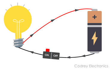
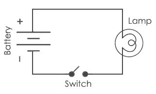
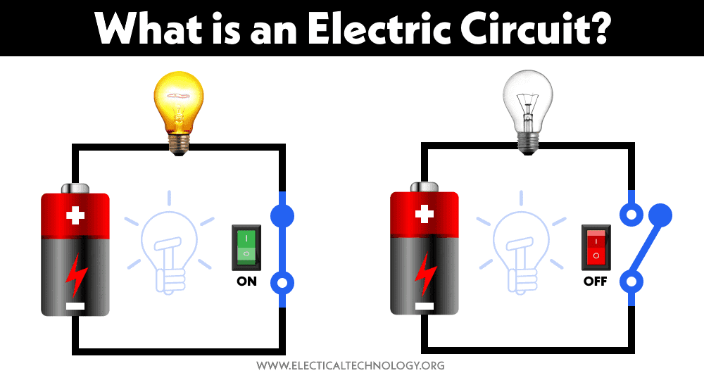
If you still can’t follow my lead, then to make it super easy, you can check the illustration below. This is the simple electric circuit implementation where we build a flashlight. This simple electric circuit represents basic components of an electric circuit.
In the circuit above, you can find all the three main elements of what form an electrical circuit.
The switch is only an addition to the circuit to control when the lamp is ON or OFF.
If the switch is open then there is no current flowing in the circuit and the lamp is OFF because the circuit is open-circuit. When we close the switch the circuit becomes closed circuit and current is flowing in the circuit then turning ON the lamp.
Now you have understood the term of electrical circuit definition. Keep in mind that an open-circuit can be considered as an electrical circuit, but it can’t make the electric current flow. And it is common sense that you have to draw the circuit in the straight line so you can analyze the circuit better.
How Does Electric Circuit Work?
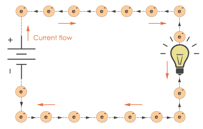
An electric circuit can work if the circuit is a closed-loop, then the current can flow through the system. One thing to remember, we need the electrons to be able to move throughout the circuit, from the positive pole to the negative pole of a power source.
What is circuit?
An electrical circuit is a path or line where electric current can flow through. The usage of a battery or any power source will produce a force to make the electrons move through end to end of a path.
The simplest example of interconnection is a flashlight circuit. The circuit has three basic elements: a lamp, connecting wires (or conductor wires), and a battery.
If we don’t learn about electrical engineering, we may find it useless.
Now let us apply interconnection to these things. Connecting them all together with the right decision will give us a flashlight.
Electronic and Electric Circuit Symbols
If you are designing, analyzing, or fixing an electrical circuit, you need to know every electronic component along with the electronic symbol in the circuit or every electric circuit symbol you should use. When we are dealing with a circuit, we will most likely deal with its circuit diagram.
Circuit diagram shows the connection of a bunch of electrical components in that circuit. You will absolutely need this to do your job very well. Imagining the circuit without drawing it is very hard, especially for the complex circuit.
The electronic symbols can be divided into:
We will learn every symbol above in a brief explanation to make this thing fast.
Connection wire symbols
We will find a lot of intersections of wires in a circuit. Make sure to understand what are the types of intersection here,
Wire
We use this to connect component to component and make an electrical circuit. This is a conductor as a path for the current to flow. The symbol is very simple, just a straight line.
Joined wire
The symbol is the ‘dot’ on the ‘crossroads’. Sometimes it is called a node, since one of the Kirchhoff laws uses this term.
Unjoined wire
In a complex circuit like a circuit which has a feedback sensor, this wire crossing but not joining is a common thing. This crossroad is not connected at all. We can use this curve symbol to show that these wires are not connected. The example on the left is also the same because we don’t use the “dot” but sometimes it can be misread.
Below is the symbol difference of joined wire and unjoined wire.
Power circuit symbols
This element energizes a circuit with either voltage or current.
Cell
The symbol is two lines, the larger one indicates the positive polarity while the smaller one indicates the negative polarity. This element provides electric voltage.
Battery
You should have known this already. The indicator of the polarity is the same with the cell. This element provides electric voltage.
Solar cell or photovoltaic cell
This element converts the solar energy into electrical energy.
DC supply
Supplies the electrical energy in direct current form. Battery also uses this symbol.
AC supply
Supplies the electrical energy in alternating current form.
Fuse
A circuit protection to prevent a blow up if a fault happens. This component can cut the circuit if the current is too high and exceeds the fuse capability.
Transformer
Two wire coils and connected by an iron core. Transformer can step up or step down AC voltage. This component uses the electromagnetic force.
Ground (earthing)
Earth or ground is used to prevent a zap in the circuit when touched.
Below is the symbol of cell, battery, solar cell, dc and ac supply, fuse, transformer, and grounds.
Output devices symbols
This element converts the electrical energy into different forms of energy.
Lamp (lighting and indicator)
A transducer to emit light as an illumination or just a simple indicator.
Heater
A transducer to convert electrical energy into heat.
Motor
A transducer to convert electrical energy into mechanical and kinetic energy.
Bell and buzzer
A transducer to convert electrical energy into sound output.
Below is the symbol of lamp, heater, motor, and bell-buzzer.
Switch symbols
This element is used to control the current flow in the circuit.
NO (Normally Open) switch
A push button which is in a closed state when pressed. It means if we push the button, the current will flow. Do you remember how to turn on and off a flashlight? This is the symbol of it. It may be an electrical switch or analogue switch.
NC (Normally Close) switch
A push button which is in an open state when pressed. It means if we push the button, the current will stop flowing.
Single Pole Single Throw (SPST) switch
The current will flow when the switch is in a close state.
Single Pole Double Throw (SPDT) switch
The two-condition switch which is able to switch the current flow depends on the route.
Double Pole Double Throw (DPDT) switch
This switch can be applied as a reversing switch for a motor.
Relay
The famous electrical switch has so many types of relay.
Below is the symbol for NO and NC switches, SPST, SPDT, DPDT, and relay.
Resistor symbols
This component is used to control the current in the circuit. Resistor provides resistance in the circuit, limiting how much current flows. There are several types of resistor.
Resistor
This prevents the flow of charge to a certain degree.
Rheostat variable resistor
This is used to control the lamp brightness and motor speed.
Potentiometer variable resistor
This variable resistor has 3 ports and one of them is used as a transducer converting position to an electrical signal. Other words, this is used for Analog-to-Digital Converter.
Preset variable resistor (trimmer)
This variable resistor uses a screwdriver to be set to adjust the resistance.
Below is the symbol for resistor, rheostat, potentiometer, and trimmer.
Capacitor symbols
This component is used to provide capacitance in the circuit. There are several types of capacitor.
Nonpolar capacitor
This capacitor doesn’t have polarity and is able to charge electric voltage.
Polar capacitor
The polarity needs to be connected in the correct way and this capacitor has larger capacitance.
Variable capacitor
A variable capacitor as a radio tuner for example.
Trimmer variable capacitor
We can set the capacitance for the capacitor and leave it to work.
Below is the symbol for nonpolar, polar, variable, and trimmer capacitors.
Inductor symbols
The inductor itself has some version of it such as,
Air core inductor
An inductor which has no core or air core.
Iron core inductor
An inductor which has iron as its core.
Ferrite core inductor
An inductor which has ferrite as its core.
Variable core inductor
We can adjust the inductance for this type.
Below is the symbol for air core, iron core, ferrite core, and variable core inductors.
Diode symbols
Diode is a component to prevent the current flow in the opposite direction. There are several types of diode.
Diode
Only allows the current flow in the desired direction.
LED (Light Emitting Diode)
A diode which is able to emit light when the current flowing passes this diode.
Zener diode
This type works just as opposite as the normal diode one and can be used to maintain a fixed voltage.
Photodiode
Diode with high sensitivity to the light.
Below is the symbol for diode, LED, zener diode, and photodiode.
Transistor symbols
You would have known about this one, we will just read the brief explanation about this semiconductor component. You can use this as an amplifier or a switch.
Transistor NPN
Transistor with NPN pin
Transistor PNP
Transistor with PNP pin
Phototransistor
Transistor with high sensitivity to the light.
Audio symbols
This element converts the electrical energy into sound or other way around.
Microphone
Convert sound to electric signals.
Earphone
Device to listen to audio in the form of an electric signal privately.
Loudspeaker
Convert electric signal into audio output to be transmitted in the open air.
Piezo transducer
Converting pressure force to electrical energy.
Amplifier
To amplify electrical signals.
Antenna
To receive or transmit the signals.
Meter symbols
Meters are the instrument to measure any parameter in the electrical circuit.
Voltmeter
Or voltage meter is a tool to measure the electric voltage.
Ammeter
Ammeter is a tool to measure the amperage of electric current.
Galvanometer
A sensitive tool using an armature and a set of magnets.
Ohmmeter
Tool to measure the resistance, measured in ohm. The Ohm itself is very important for us because it is related to the Ohm’s law and basic electrical theory. The ohmmeter symbol is the symbol of Ohm itself.
Oscilloscope
A digital meter which is able to display the waveform as an electrical signal. We can tune the period, measurement scale, and even save the image.
Sensor symbols
This element is capable of receiving energy and converts it into electrical signals.
Light Dependent Resistor (LDR)
A component which is able to convert light into electrical signal or voltage.
Thermistor
A component which is able to convert the temperature into electrical signal or voltage.
Logic gate symbols
Logic gates are used to design a digital sequence program for electronics.
Integrated Circuit (IC)
This type has various applications and is very convenient to use. Usually, it is drawn with a rectangular shape and some ports.
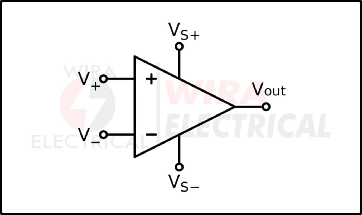
Operational Amplifier
It is also popular with Op-amp and is illustrated with a triangle shape along with three ports: two as inputs and one as output.
Types of Electrical Circuits
If we are talking about the types of electrical circuits, we will find the two very basic types. The first one is a series circuit and the second is a parallel circuit, or you can change the arrangement, it won’t be that important. Their basic difference is how many loops they have in their circuit. You can check the example below, you will understand it faster.
Series circuit
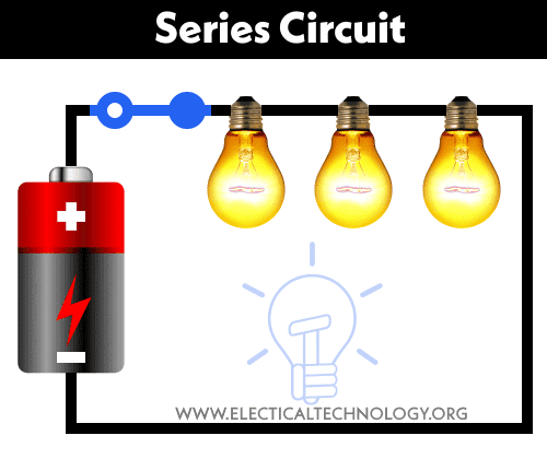
The series circuit has one loop from end-to-end, from the source back to the source. If we cut the wire in any position or remove one of the elements except for the source, that spot is an open circuit and the current will stop flowing.
You can see the example below.
In a series circuit, the current in the circuit will be the same for every element in there. Summary, the current passing through R1 and R2 will be the same value. If we remove one of the resistors then the circuit will be an open-circuit and the current will stop flowing.
That’s the essential thing about series circuits. Another simple example of a series circuit is a flashlight. We just need to connect a battery, switch, and lamp in one path. Once you open the switch then the lamp will die.
Parallel circuit
The parallel circuit has more than one loop for the current to flow. If we cut the wire in any position or remove one of the elements except for the source, that spot is an open circuit but the current can still flow through another loop.
You can see the example below.
In a parallel circuit, the current in the circuit will be the sum of all the current in every loop. The current in each loop depends on the load in that loop. If we remove the R1 then the current through R1 will start flowing through the R2. If we remove the R2 then the current through the R2 will start flowing through R1.
Summary, if we cut one loop then the current will start flowing in another loop as long as there is a loop which is still a close-circuit.
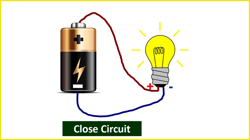
Close circuit
This is the circuit where the circuit is connected end to end and the electric charges are able to move through the system.
This circuit is the same with the flashlight circuit when you turn on the switch.
Open circuit
You will find something strange in this circuit where the circuit is not connected in a specific place. Electric charges are not able to move in this circuit.
The example of this circuit is when you turn off the switch of a flashlight.
Short circuit
A short circuit is a circuit when the current is too large. This can occur if there is no load in a conductor wire connected to a power source.
It is like connecting the positive polarity and negative polarity of a battery with copper wire.
Electric Circuit AC and DC
We will encounter a lot of electric circuits in life applications. The application of an electric circuit will result in a different type of electrical circuit. For starting, the electric circuit types will differ as :
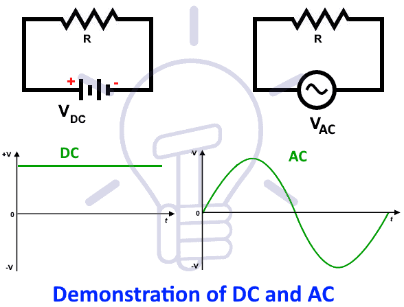
The difference between these two is the source of the corresponding electric circuit. If the dc source energizes the circuit, it will be a dc circuit.
On the other hand, an ac circuit happens if the ac source energizes the circuit. Make sure to read both before leaving to advance matters.
Frequently Asked Questions
What is an electrical circuit
Electrical circuit is a path for transmitting electrical charge. An electrical circuit capable of delivering electrical energy and absorbing electrical energy.
What is electricity
Electricity is called physical phenomena related to the presence of matter which has the property of electric charge. Ages ago, electricity was considered not related to magnetism.
What is an electric circuit short definition?
An electric circuit is an interconnection of several electrical components so that the electric charge can flow along in a closed path or closed circuit.
What are the 5 components of an electric circuit?
The following most commonly used components are:
1. Resistor to provide resistance
2. Inductor to provide inductance
3. Capacitor to provide capacitance
4. Transistor
5. Diode
What is electrical?
Electrical means operating by electricity or generating electricity.
What is a simple electric circuit?
A simple electric circuit can be built from a battery, a resistor, and a lamp to make a simple flashlight.
How does a circuit work?
Energy from the battery is transferred to the circuit’s components by an electric current. Nothing in this procedure “uses up” any current. Negatively charged electrons, which are constantly present in the circuit’s wires and other parts, are the most common type of moving charged particle.
What are types of electric circuits?
There are five types of electric circuits: short circuit, open circuit, series circuit, parallel circuit, and closed circuit.
What are electrical circuit components?
No matter where it is or how big or little it is, every electric circuit contains four fundamental components: an energy source (AC or DC), a conductor (wire), an electrical load (device), and at least one controller (switch). Imagine what happens when a room light is turned on.
What is circuit definition in electronics?
A circuit in electronics is a complete circular pathway through which the electricity flows. A current source, conductors, and a load make up a straightforward circuit. In a broad sense, the word “circuit” can refer to any permanent path through which electricity, data, or a signal can pass.
3 thoughts on “What is An Electrical Circuit – Simple Explanation”
Great website! I am loving it!! Will come back again. I am bookmarking your feeds also
Boa noite turma, provavelmente disparar um torpedo web gratuito está cada vez mais difícil devido a restrição das operadoras de telefone. Há ainda serviços de terceiros (sites) que prometem entregar meu SMS mas quase nunca chegam ao usuário final. Alguns como o Mundo oi e o Oi Torpedo funcionam mas e para as outras operadoras? E os que prometem que enviam e nada chega. Para onde está indo as meus SMS? E para a Tim, Vivo? Alguma Idéia? Ou significa ter de desembolsar?. É só um desabafo, realmente está difícil achar bons sites para enviar SMS de graça.
You made some decent points there. I regarded on the internet for the difficulty and located most people will go together with together with your website….
What is an Electrical Circuit?
Electrical circuit is an interconnection of electrical components. An electrical circuit consists of batteries, resistors, inductors, capacitors, switches or transistors. An electrical network consists of a closed loop. A circuit is a closed path where electrons flow in a wire. As long as the copper wire is allowed to itself, the electrons drift between the atoms but never leave the copper.
However, when we connect this copper wire to a battery the free electrons will be driven towards the positive terminal of the battery. This pushing force is called Electromotive force (E.M.F). The E.M.F. is expressed in volts. And usually, it is called voltage. As a result of this voltage, an electron motion takes place. This motion is known as electron current or electric current. We can measure current by connecting an ammeter between copper wire and voltage source.
A complete circuit is a never-ending loop of electrons. If we take a wire and loop it around, it forms a continuous path in which electrons can flow forever. This is a primary concept of a circuit.
An electric circuit mainly consists of
There are some basic properties of electrical circuits and they are:
Circuit Diagram
A circuit diagram is a visual display of an electrical circuit. There are mainly two types of circuit diagrams:
A pictorial circuit diagram
Circuit Diagram Symbols
There are hundreds of symbols for the circuit diagram. Some basic symbols are:
| Name | Symbol |
|---|---|
| Resistor |  |
| Capacitor |  |
| Cell |  |
| Battery |  |
| LED |  |
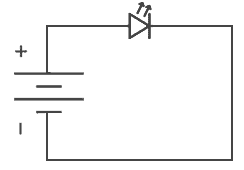
Suppose we want to draw a simple circuit in which battery is connected to LED in such a way that positive terminal of the battery is connected to positive terminal of LED and negative terminal of the battery is connected to negative terminal of LED. Then it can be represented as:
Types of Circuits
There are basically three types of circuits:
Open circuit
If in a simple circuit one terminal is disconnected, then there is no flow of current through that circuit. This is said to be an open circuit or no load condition.
An open circuit
Closed circuit
An electric circuit has a source of Electromotive force and a load. This load acts as a conductor path. If the current flows through the load it is considered as a closed circuit. If in a simple circuit, current can flow from one terminal of the battery to another without any discontinuation is said to be closed circuit.
A closed circuit
Short circuit
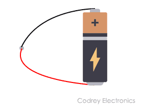
If the positive terminal of the battery is directly connected to the negative terminal without any resistance between them is said to be a short circuit.
A Short Circuit
Other than the above circuits, components in an electric circuit can be arranged in two different ways and that are in series connection and in parallel connection.
Series Circuit
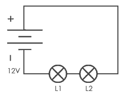
If in a circuit, components are connected in series then the circuit is known as a series circuit. In a series circuit, current through each component is same and voltage supplied is the sum of the voltage across each component. If a wire joins the battery to one lamp, to the next lamp and then back to the battery, the lamps are said to be connected in series.
Series connection of two lamps
Parallel Circuit
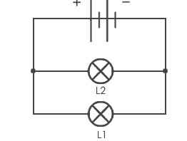
If in a circuit, components are connected in parallel then the circuit is known as parallel circuit. In a parallel circuit, the voltage across each component will be same and total current applied is the sum of current through each component. If a lamp is connected to the battery and another lamp is connected in a separate loop with first lamp, then lamp is connected in parallel connection.
Parallel connection of two lamps
Here, the voltage across each bulb would be the same as the voltage applied by the battery. Current across each lamp would be divided means if we appply 5A to the circuit, 5A will be the current flowing through each lamp.
Thus this is how series and parallel circuits work and they have their own current and voltage dividing properties.
Electric circuits are all around us, in our mobile phones, in our computers, in fan and also in the torch. It is difficult to assume the practical use of electricity without circuits. We are all dependent on these complex circuits around us.
Types of Electric Circuits: All Classification with Application
Table of Contents
Types of Electric Circuit- Closed circuits, open circuits, short circuits, series circuits, and parallel circuits are the five main types of electric circuits. Let us learn and comprehend using definitions, examples, and symbols in depth. The term “electric network” refers to a collection of distinct electric elements or components that are linked in some way. A complex network is a circuit that incorporates several electrical elements such as resistors, capacitors, inductors, current sources, and voltage sources (both AC and DC). Simple ohm’s law or Kirchhoff’s laws are insufficient to address these types of networks. To put it another way, we solve these circuits using specialized techniques like Norton’s Theorem, Thevenin’s Theorem, Superposition Theorem, etc.
What is an Electric Circuit?
An electrical circuit is a network of components used for energy storage, transmission, and conversion. One or more sources supply energy to a circuit, and one or more sinks remove it. Energy is converted from thermal, chemical, electromagnetic, or mechanical form to electrical form in the sources; the process is reversed in the sinks. Energy is carried through an electrical circuit through the use of electrical charge and the medium of magnetic and electric fields. Circuits come in a variety of forms.
A path for transferring electric current is known as an electric circuit. An electric circuit consists of a device, such as a battery or a generator, that provides energy to the charged particles that make up the current; equipment that uses current, such as lights, electric motors, or computers; and the connecting wires or transmission lines. Ohm’s law and Kirchhoff’s rules are two essential laws that quantitatively define the behavior of electric circuits.
Electric circuits can be categorized in a number of ways. A direct-current circuit carries just one direction of the current. In most domestic circuits, an alternating-current circuit transmits current that pulsates back and forth multiple times per second. A series circuit is one in which the entire current travels through all of the components. A parallel circuit has branches that split the current such that just a portion of it passes through each branch. In a parallel circuit, the voltage, or potential difference, between each branch is the same, but the currents may differ.
Each light or appliance in a household electrical circuit, for example, receives the same voltage, but each draws a variable amount of current based on its power requirements. A series of comparable batteries connected in parallel generates more current than a single battery while maintaining the same voltage.
An electric circuit is a combination of transistors, transformers, capacitors, connecting wires, and other electrical components contained within a single device, such as a radio. One or more branches in a mixture of series and series-parallel layouts can make up such complicated circuits.
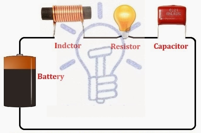
A circuit, often known as an electrical circuit, is a closed-loop channel that provides a current return path. This is a narrow conducting channel through which current can flow.
Types of Electric Circuits
There are many types of electric circuits including:
We’ll go through each of them briefly below.
What is Open Circuit? Diagram & Example
What is Closed Circuit? Definition & Example
What is Short Circuit? A Clear Definition & Protection Guide
What is Series Circuit? Definition & Example
Series Circuit
All of the electrical parts (voltage or current sources, inductors, capacitors, resistors, and so on) are connected in series in this circuit, which means there is only one path for electricity to go and no additional branches. A series circuit is made up of multiple resistances that are connected one after the other. An end-to-end or cascade connection is another name for this type of connection. The flow of current follows a single path.
Properties of Series Circuit
Every resistance is crossed by the same current. The total of the various voltage falls across the resistances is the supply voltage V.
The total of the various resistances is equal to the comparable electrical resistance. Individual resistances are overwhelmed by the equivalent resistance (R > R1, R > R2, …., R > Rn).
Parallel Circuit
All of the electrical elements in this circuit (voltage or current sources, inductors, capacitors, resistors, and so on) are linked in parallel, i.e. there are numerous channels for electricity to travel down, and the circuit’s minimum branches are two. A parallel circuit is one in which many resistances are connected across one another in such a way that one terminal of each resistance is connected to form a junction point, and the remaining end is also connected to make another point.
Properties of Parallel Circuits
A similar potential difference is shared by all resistances at the same time. The total current is divided into the number of parallel routes equal to the number of resistances. The sum of all the individual currents is always the aggregate current.
The reciprocal of a parallel circuit’s equivalent resistance is equal to the total of the reciprocals of the individual resistances. The smallest of all resistances is the equivalent resistance (R Series-Parallel Circuit
A series-parallel circuit is one in which certain circuit elements are connected in series while others are connected in parallel. To put it another way, this is a circuit that combines series and parallel circuits.
Star-Delta Circuit
This is not a parallel, series, or series-parallel circuit. Electrical elements are connected in this circuit in such a way that the configuration is undefined in terms of Series, Parallel, or Series Parallel. The Star-Delta Transform or Delta-Star transformation can be used to solve these types of circuits.
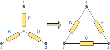
More derived circuits of the Series, Parallel, and Series-parallel circuits are listed below:
All of the above-mentioned components or elements can be connected in series, parallel, or series-parallel configurations in the circuits above. Visit here to see all of the different types of electric circuits completely.
Let’s look at some more electric circuits that you should be familiar with before beginning to study an electric circuit or network.
Linear & Non-Linear Circuits
Linear Circuit
A linear circuit is an electric circuit with constant circuit parameters such as resistance, inductance, capacitance, waveform, and frequency. In other terms, a linear circuit is one whose parameters do not change with regard to current and voltage.
Non-Linear Circuit
A non-linear circuit is one in which the parameters vary in relation to current and voltage. In other terms, a nonlinear circuit is one in which the circuit parameters (resistance, inductance, capacitance, waveform, frequency, and so on) are not constant.
Unilateral & Bi-lateral Circuits
Unilateral Circuits
In unilateral circuits, the function of the circuit changes as the supply voltage or current changes direction. To put it another way, a unilateral circuit only permits the current to pass in one direction. Because it does not perform rectification in both supply directions, the diode rectifier is the best example of a unilateral circuit.
Bi-Lateral Circuits
The property of a circuit in a bi-lateral form does not change as the supply voltage or current changes direction. Bi-lateral circuits, in other terms, allow current to flow in both directions. The best description of a bi-lateral circuit is a transmission line because the circuit parameters stay constant regardless of which direction the supply comes from.
Circuit’s Parameters, Constants and Related Terms
Circuit parameters or constants refer to the various components or elements used in electric circuits, such as resistance, capacitance, inductance, frequency, etc. These variables can be grouped or dispersed. These parameters can determine the specification of each circuit which are summarized below:
Active Circuit
An active circuit is a circuit that contains one or more EMF (Electro Motive Force) sources.
Passive Circuit
The term “passive circuit” refers to a circuit that has no EMF sources.
Open Circuit
An open circuit is one in which there is no return channel for current to flow (i.e. one that is not completed). In other terms, an open circuit is one in which the voltage tends to 0zero and the current approaches to infinity.
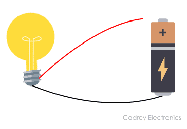
An open circuit occurs when a circuit contains a damaged electrical wire or electronic component or when the switch is turned off. The bulb is not lighting in the diagram below because either the switch is turned off or the electrical line is faulty.
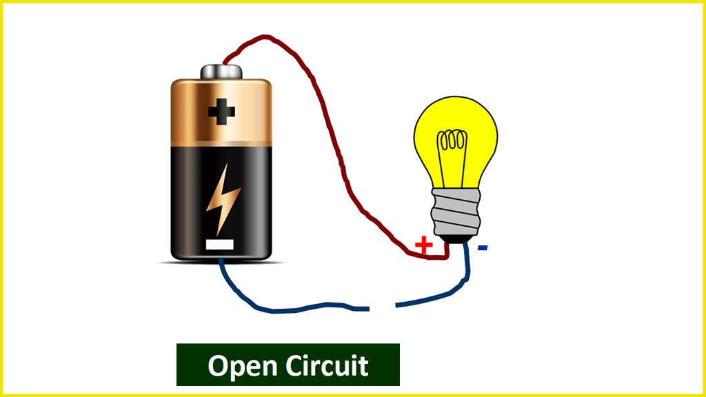
A circuit with an open switch and a light bulb attached to the battery is an example of an open circuit. As a result of the open circuit, the bulb will not light.
What is Parallel Circuit? Definition & Example
Short Circuit
A short circuit is a circuit that has a return channel for current to flow in it (i.e. completed circuit). A short circuit is a circuit in which the voltage tends to infinity and the current tends to zero.
A short circuit occurs when both points (+ and –) of a voltage source in a circuit become connected for any reason. In this case, the maximum current begins to flow. Short circuits occur when conducting electrical lines become joined or even due to shorting in the load.
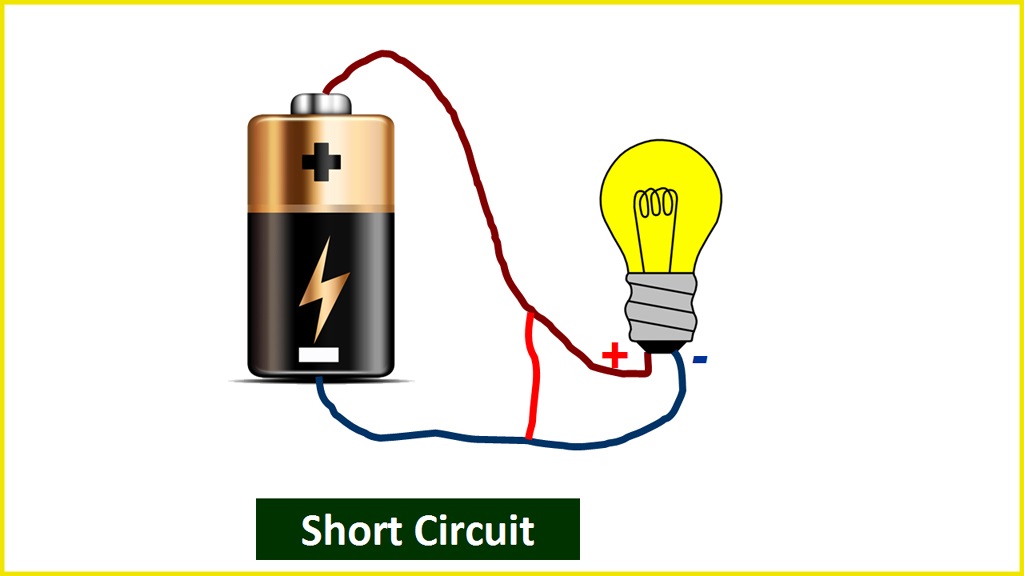
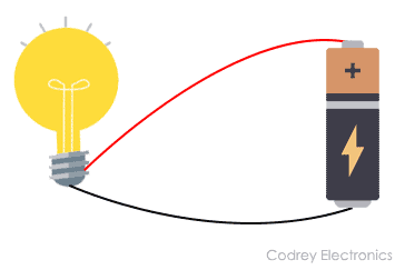
A circuit with a close switch and a light bulb attached to the battery is an example of a short circuit. As a result of the completed circuit, the light illuminates.
Closed Circuit
Closed Circuit is the term used when a load in a circuit functions on its own. The value of the current flow, in this case, is determined by the load.
Parts of Electric Circuits and Networks & Other Related Terms
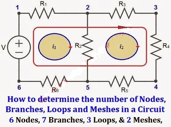
Node
A node refers to the point or junction where two or more circuit elements (resistor, capacitor, inductor, etc.) connect.
Branch
Branch refers to the segment or section of a circuit that occurs between two junctions. One or more parts can be joined in a branch, which has two endpoints.
Loop
A loop is a closed channel in a circuit that can contain more than two meshes, i.e. a loop can contain multiple meshes, but a mesh can only include one loop.
Mesh
Mesh is a closed loop that does not contain any other loops or paths that do not contain any other pathways.
What is an Electric Circuit? Types of Circuits and Network
Electric Circuit, Network, Complex Circuits and other Types of Circuits
Table of Contents
What is an Electric Circuit?
An electric circuit is a closed loop network which provides a return path for the flow of current. Or a closed conducting path in which current can flow is called a circuit. An electric circuit is also known as electrical network or electrical circuit.
An electrical circuit is the combination of different active and passive components such as resistors, capacitors, inductors, diodes, transistors etc. which form an electrical network. In a closed-loop circuit, the electric current flows from the source (such as battery) in the conducting material (e.g. wires and cables) to the load (i.e. light bulb) and hence returns back to the source.
What is an Electrical Network?
A combination of different electric elements and components which are connected in any way (simple or complex configuration) is called an electric network. It is the same term used for an electric circuit but most commonly associated with the complex networks which are solved by network theorems.
Complex Networks
A circuit which contains many electrical elements such as resistors, capacitors, inductors, current and voltage sources (both AC and DC) where all the circuit components and elements are complexly configured is called a complex network. These kinds of networks can’t be solved easily by simple Ohm’s Law or Kirchhoff’s laws. If so, the number of equations will be noticeable more.
The easiest way to solve and analyze a complex network is using specific techniques such as network theorems i.e. Norton’s theorem, Thevenin’s theorem, Superposition theorem, star – delta transformation, Supernode and supermesh circuit analysis etc.
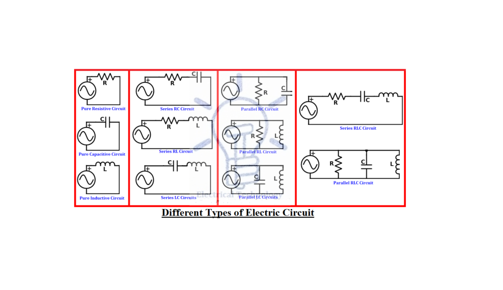
Types of Electric Circuits
There are many types of electrical circuits such as:
We will briefly discuss one by one as follows.
Open Circuit
A circuit which has no return path for current to flow in it (i.e. which is not completed) is known as an open circuit. In other words, a circuit where voltage tends to the EMF (of generating source) and no current is flowing at all is called an open circuit.
Example of an open circuit: A circuit with an open switch or blown fuse where the light bulb connected to the battery. So the bulb won’t glow as the circuit is not completed i.e. it is an open circuit and there is no flowing current in it.
Closed Circuit
A circuit which has a return path for current to flow in it (i.e. completed circuit) is known as closed circuit.
Example of a short circuit: A circuit with a close switch where the light bulb connected to the battery. So the bulb glows as current is flowing in the filament of the bulb due to the completed circuit.
Short Circuit
A circuit which has a return path for current to flow in it where the value of resistance = zero. (i.e. completed or closed circuit without connected load) is known as short circuit. In other words, A circuit where voltage tends to zero and current tends to infinity is called a short circuit.
Example of a short circuit: A circuit with a close switch without load connected to the supply voltage. In other words, when a Phase or Line wire touches the Neutral wire without a load between them. In that case, the fuse will blow or the circuit breaker will trip. In absence of proper protection, the short circuit may damage the appliance or cause a very serious injury.
Series Circuit
In this circuits, all the electrical elements (Voltage or Current sources, inductors, capacitors, resistors etc) are connected in series i.e. There is only one path for traveling electricity e.g. these are single branch circuits.
Parallel Circuit
In this circuits, all the electrical elements (Voltage and Current sources, inductors, capacitors, resistors etc) are connected in parallel i.e. There are many paths for traveling electricity and the minimum branches in this circuit are two.
Series-Parallel Circuit
If circuit elements are series connected in some parts and parallel in others, that would be a series-parallel circuit. In other words, this is a combination of series, parallel and series-parallel circuits.
Following are more derived circuits of the Series, parallel, and Series-parallel circuits
These all circuits are shown in fig below.
Click image to enlarge
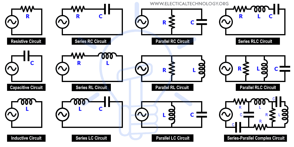
In the given circuits, all the above-mentioned components or elements may be connected in series, parallel, or in both combinations of series-parallel configuration.
Star-Delta Circuit
These kinds of circuits are connected in Star connection or delta connection. In these circuits, electrical elements are connected in a way that is undefined in terms of series, parallel or series-parallel configuration. Star delta circuits can be solved by Star to Delta and Delta to Star transformation.
Before analyzing an electric circuit and network, you must know the following useful terms associated with electric circuits which specify the nature and characteristics of a circuit.
AC Circuit
A circuit containing an AC supply source of voltage is known as AC circuits. The supply sources for example are alternator and synchronous generators.
DC Circuit
A circuit containing a DC supply source of voltage is known as DC circuits. The supply sources for example are batteries and DC generators.
Single Phase Circuits
The AC power where all the voltages have the same sinusoidal pattern at a specific time period is known as single phase AC supply. In single phase AC circuits, only two wires (known as phase or line and Neutral) are needed to complete the circuit.
Polyphase Circuits
Poly means more than one. As the name suggests, the AC power where there are three sinusoidal voltages having 120° phase difference. In three phase AC circuits, three phase three wires or three phase four wires are needed to complete the circuit.
Circuit’s Parameters, Constants and Related Terms
Different components or elements which are used in electric circuits are called circuit’s parameters or constants i.e. resistance, capacitance, inductance, frequency etc. These parameters can be lumped or distributed.
Active Circuit
A circuit which contains on one or more EMF (Electromotive force) sources is called Active Circuit
Passive Circuit
A circuit, in which no one EMF source exist is called Passive Circuit
Linear & Non Linear Circuits
Linear Circuit
A linear circuit is an electric circuit in which circuit parameters (resistance, inductance, capacitance, waveform, frequency etc) are constant. In other words, a circuit whose parameters are not changed with respect to current and voltage is called a linear circuit.
Non Linear Circuit
A nonlinear circuit is an electric circuit whose parameters are varied with respect to current and voltage. In other words, an electric circuit in which circuit parameters (resistance, inductance, capacitance, waveform, frequency etc) are not constant, is called a Non-linear circuit.
Unilateral & Bi-lateral Circuits
Unilateral Circuits
In unilateral circuits, the property of circuit changes with the change of direction of supply voltage or current. In other words, a unilateral circuit allows the current to flow only in one direction. Diode or rectifier is an example of a unilateral circuit because it does not perform the rectification in both directions of supply.
Bi-lateral Circuits
In bilateral circuits, the property of circuit does not change with the change of direction of supply voltage or current. In other words, a bilateral circuit allows the current to flow in both directions. Transmission line is the best example of a bilateral circuit because, providing the supply voltage from any direction (starting end or finishing end), the circuit properties remain constant.
Related Terms to Electric Circuits and Networks
A point or junction where two or more circuit’s elements (resistor, capacitor, inductor etc) meet is called Node
Branch
A part or section of a circuit which is located between two junctions is called a branch. In a branch, one or more elements having two terminals can be connected.
A closed path in a circuit where more than two meshes can occur is called loop i.e. there may be many meshes in a loop, but a mesh does not contain one loop.
A closed loop which contains no other loop within it or a path which does not contain other paths is called Mesh.
We use different theorems to solve complex networks. Generally, Complex networks can be solved by the following two methods.
We will discuss these methods one by one in our next post with details.


