What is the ammeter used for
What is the ammeter used for
What Is an Ammeter? | Working Principle of Ammeter | The Ultimate Guide
As we all know, an ammeter is an electronic device used to measure currents; thus, it is connected to a measurement system. In the same way, an ammeter is nothing but an ampere measurement. Ampere is a no unit for measuring a current. This meter is used to measure the current.
There are generally two types of power, one is Alternating current (AC), and the other is Direct current (DC). The Alternating current converts the current into regular intervals while the direct current flows in one direction.
In today’s article, we will see what is the working principle of what an ammeter is and about, its types, and much more.
What is an Ammeter?
Definition: An instrument or device used to measure the current flowing in an electric circuit. Such an instrument is called an ammeter. The current SI unit is ampere. This is also known as an ammeter or ampere meter as it measures the current. The internal resistance of this device is usually ‘0’, which is also practically correct as it has a small amount of internal resistance. The measurement range of this instrument depends mainly on the resistance value.
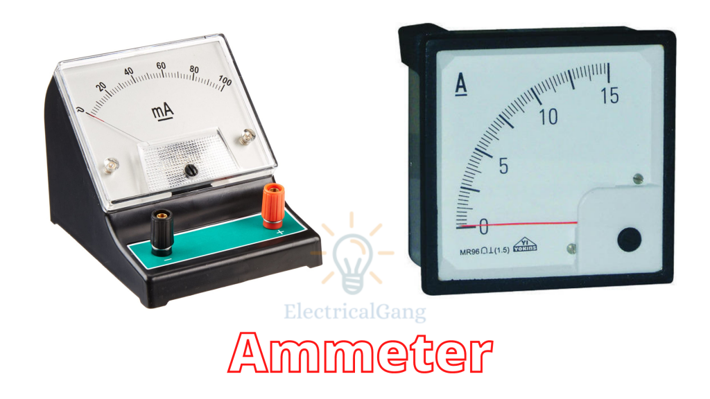
The figure of the ammeter is as follows:
Working Principle of Ammeter:
The working principle of an ammeter depends on the current flowing along with its resistance. Very little impedance is used inside the ammeter as it must drop the least amount of voltage attached to it. The ammeter is connected to the series of circuits as the current in the series circuit is the same.
The main function of this tool is to measure the flow of current with the help of a set of coils. Inside this coil, there is very little resistance and inductive reaction.
Types of Ammeters:
The ammeter is classified into six parts based on its application as follows:
| Sr. No. | Types of Ammeters |
| #1 | Moving the coil |
| #2 | Electrodynamic |
| #3 | Moving-iron |
| #4 | Digital Ammeter |
| #5 | Hotwire |
| #6 | Integration |
#1. Moving the coil:
This type of meter is used to measure both AC power and DC power. This device uses magnetic deflection, where the current will flow with the help of a coil to rotate in a magnetic field. The coil in this device rotates freely between the permanent magnet poles.
#2. Electrodynamic:
An electrodynamic ammeter consists of a rotating coil rotating in a field created with the help of a fixed coil. With the help of this instrument, AC and DC power can be measured with an accuracy of 0.1 to 0.25%. This is more reliable when compared to a rotating coil and a fixed coil. The calibration of this device is the same for AC and DC.
#3. Moving-iron:
Moving-iron type ammeters are used to calculate AC power and voltages. This system consists of pieces of soft iron specially made in a movable system, which are acted upon by a fixed coil electromagnetic force made of wire. Devices of this type are classified into two parts, one is repulsion, and the other is attraction.
This device uses different components such as a moving element coil, control, damping, and reflective torque.
#4. Digital Ammeter:
This type of device is used to measure the current in the ampere whose value is displayed on the display. A shunt resistor is included in its design to create a calibrated voltage of such a device, which is in proportion to the current flow.
This device provides information about load and continuity on the current circuit so as to help the customer to overcome variable loads and trends.
#5. Hotwire:
This is used to heat and spread the wire with the help of AC power and DC power, which is known as a hot wire. The working principle of this is that it extends the wire by providing the effect of heat from the current supply. This makes it possible to use both AC and DC flows.
Ammeter Circuit Diagram Or Ammeter Diagram:
The construction of the ammeter is made possible by both series and shunt. In the figure below, you can see the meter made in both series and shunt, which we will discuss in detail.
First of all, let’s talk about the series.
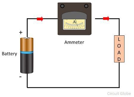
First of all, let’s talk about the series. Once this meter is connected in series, all the current of the circuit passes through it. So the power consumption is due to its internal resistance and parameter current within this meter. This circuit uses low resistance so that low voltage drop in the circuit.
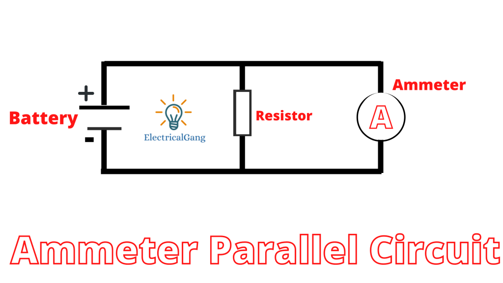
The resistance is kept low in the parallel ammeter circuit so that the total current will flow from the ammeter and drop low voltage across the device. When a high current from the circuit passes through this device, its internal circuit can be damaged. The shunt resistance is connected in parallel to the emitter to avoid the problem of high current.
If a high current passes through the circuit, then the main current passes through this shunt resistance. This resistance does not prove to be a hindrance to the function of the device.
Applications of Ammeter:
The uses of the ammeter is as follows:
Frequently Asked Questions (FAQs):
What is the principle of ammeter and voltmeter?
The voltmeter is connected in parallel to measure its voltages, while the ammeter is connected in series to measure its amperage. In the heart of most analog meters is a galvanometer, an instrument that measures current flow using the movement or bend of a needle.
What are the applications of an ammeter?
The application of the ammeter is as follows:
What are the different types of an ammeter?
The ammeter is classified into six parts based on its application as follows:
| Sr. No. | Types of Ammeters |
| #1 | Moving the coil |
| #2 | Electrodynamic |
| #3 | Moving-iron |
| #4 | Digital Ammeter |
| #5 | Hotwire |
| #6 | Integration |
What is the ammeter with a diagram?
This is also known as an ammeter or ampere meter as it measures the current. The internal resistance of this device is usually ‘0’, which is also practically correct as it has a small amount of internal resistance. The measurement range of this instrument depends mainly on the resistance value.
What is the ammeter symbol?
The common symbol for the ampere meter is the capital A specified in a circle. This is how the ammeter symbolizes an electric circuit.
Ammeter Working Principle:
The working principle of an ammeter depends on the current flowing along with its resistance. Very little impedance is used inside the ammeter as it must drop the least amount of voltage attached to it. The ammeter is connected to the series of circuits as the current in the series circuit is the same.
Working of Ammeter:
The resistance of an ammeter is very low. An ammeter is always connected in series with a load to measure its flowing electric current. As such, the ammeter has very low resistance, so when it is connected in series with any circuit, it does not change the current.
Digital Ammeter Working Principle:
The working principle of an ammeter depends on the current flowing along with its resistance. Very little impedance is used inside the ammeter as it must drop the least amount of voltage attached to it. The ammeter is connected to the series of circuits as the current in the series circuit is the same.
AC Ammeter Working Principle:
The working principle of an ammeter depends on the current flowing along with its resistance. Very little impedance is used inside the ammeter as it must drop the least amount of voltage attached to it. The ammeter is connected to the series of circuits as the current in the series circuit is the same.
Like this post? Share it with your friends!
About Vishnu Patil
Hey, I am Vishnu Patil and I’m an Electrical Engineer and Electrical maestro. I have more than 10 years of experience with electricals. Through ElectricalGang I want to spread my knowledge with everyone else.
Ammeter
Definition: The meter uses for measuring the current is known as the ammeter. The current is the flow of electrons whose unit is ampere. Hence the instrument which measures the flows of current in ampere is known as ampere meter or ammeter.
The ideal ammeter has zero internal resistance. But practically the ammeter has small internal resistance. The measuring range of the ammeter depends on the value of resistance.
Symbolic Representation
The capital alphabet A represents the ammeter in the circuit.
Connection of Ammeter in Circuit
The ammeter is connected in series with the circuit so that the whole electrons of measurand current passes through the ammeter. The power loss occurs in ammeter because of the measurand current and their internal resistance. The ammeter circuit has low resistance so that the small voltage drop occurs in the circuit.
The resistance of the ammeter is kept low because of the two reasons.
Types of Ammeter
The classification of the ammeter depends on their design and the type of current flows through the ammeter. The following are the types of an ammeter regarding construction.
By the current, the ammeter categorises into two types.
1. PMMC Ammeter – In PMMC instrument the conductor is placed between the pole of the permanent magnet. When the current flows through the coil, it starts deflecting. The deflection of the coil depends on the magnitude of current flows through it. The PMMC ammeter used only for the measurement of the direct current.
2. Moving Coil Ammeter (MI) – The MI ammeter measures both the alternating and direct current. In this type of ammeter, the coil freely moves between the poles of a permanent magnet. When the current passes through the coil, it starts deflecting at a certain angle. The deflection of the coil is proportional to the current passes through the coil.
3. Electro-dynamometer Ammeter – It is used for the measurement of both AC and DC. The accuracy of the instrument is high as compared to the PMMC and MI instrument. The calibration of the instrument is same both for AC and DC, i.e. if DC calibrates the instrument then without re-calibration, it is used for AC measurement.
4. Rectifier Ammeter – It is used for measuring the alternating current. The instruments using the rectifying instrument which converts the direction of current and pass it to the PMMC instrument. Such type of instrument is used for measuring the current in the communication circuit.
The instrument which measures the DC is known as the DC ammeter and ammeter which measures AC is known as the AC ammeter,
Ammeter Shunt
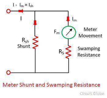
The high-value current directly passes through the ammeter which damages their internal circuit. For removing this problem, the shunt resistance is connected in parallel with the ammeter.
If the large measurand current passes through the circuit, the major portion of the current passes through the shunt resistance. The shunt resistance will not affect the working of the ammeter, i.e., the movement of the coil remains same.
Effect of Temperature in Ammeter
The ammeter is a sensitive device which is easily affected by the surrounding temperature. The variation in temperature causes the error in the reading. This can reduce by swamping resistance. The resistance having zero temperature coefficient is known as the swamping resistance. It connects in series with the ammeter. The swamping resistance reduces the effect of temperature on the meter.
The ammeter has the inbuilt fuse which protects the ammeter from the heavy current. If substantial current flows through the ammeter, the fuse will break. The ammeter is not able to measure the current until the new one does not replace the fuse.
Ammeter Working Principle & Ammeter Vs Voltmeter
Table of Contents
An Ammeter is an Electronic Device or an Instrument Which is used to measure electric current flowing through an Electric Circuit.
The current is the flow of electrons whose unit is ampere. Hence the instrument which measures the flows of current in ampere is known as ampere meter or ammeter.
The Working principle of it depends upon the resistance as well as inductance reactance. The value of resistance and inductive reactance must be very low.
It has a very low impedance as the voltage drop across the ammeter should be low. It cannot be connected in parallel because of the above-mentioned reason.
In a series connection, the current will be same. Also connecting an ammeter in parallel may result in short circuit and the current passing through ammeter might burn the instrument.
For an ideal ammeter, the impedance must be zero so that the voltage drop across the instrument is zero.
The main functions of it is used to measure current flow through a circuit.
What happens when Voltmeter and Ammeter interchange their position?
Ammeter is always connected in series because it has low resistance.
Voltmeter is always connected in parallel. because it has high resistance.
So conditions is what happens when both interchange their position..
Ammeter is connected in parallel. So it has very low resistance…current follow only low resistive path….so they act like short circuit and also there are chances of ammeter getting damaged.
Now, if Voltmeter is connected in series. Then due to high resistance no current will flow through circuit. So no voltage drop occur. Voltage in same line is zero
Ammeter vs Voltmeter
The reason for the low resistance of it is that the current flowing in the circuit can be read exactly.
When the resistance of the ammeter is low, almost all the current in the circuit is allowed to pass through the ammeter.
This allows it to read the current precisely in the circuit. If, on the other hand, the resistance of the ammeter was higher, the ammeter would read a value less than the actual value flowing through the circuit.
This is because, in this case, the ammeter itself would be opposed to the current flow.
Which has more resistance, a galvanometer, a voltmeter, or an ammeter?
For voltmeter resistance should be infinity
And for Ammeter it should be zero
How is the voltmeter and ammeter connected in a circuit?
The answer is very simple. First you have to know there basics of an ammeter and voltmeter.
An ammeter is used to measure the current passing through it, which means the current which we want to measure should flow through that meter. So there should be very low resistance, then only the current can pass through the meter, and the meter shows deflection.
Since it has low resistance if it is connected in parallel the circuit will be shorted. So we always connect an ammeter in series.
For a voltmeter it should measure the voltage across the input terminals as we know that voltage is equal in parallel connection then we should connect it in parallel with the supply or load (both means same), for a parallel connection it should have high resistance beacuse if it has low resistance then the circuit will be shorted.
So the voltmeter should be connected in parallel.
How is ammeter connected in an electric circuit?
It connected in series in an electric circuit.
What is an ammeter, voltmeter and multimeter? How are they different from each other?
Ammeter = current measurement
Voltmeter = voltage measurement
Check Out Other Important Topics
ammeter
Our editors will review what you’ve submitted and determine whether to revise the article.
Our editors will review what you’ve submitted and determine whether to revise the article.
ammeter, instrument for measuring either direct (DC) or alternating (AC) electric current, in amperes. An ammeter can measure a wide range of current values because at high values only a small portion of the current is directed through the meter mechanism; a shunt in parallel with the meter carries the major portion. In circuit diagrams, the symbol for an ammeter is a circle with a capital A inside.
Ammeters vary in their operating principles and accuracies. The D’Arsonval-movement ammeter measures direct current flowing through a coil suspended between the poles of a magnet with accuracies of from 0.1 to 2.0 percent. The electrodynamic ammeter uses a moving coil rotating in the field produced by a fixed coil. It measures direct and alternating current (by using a rectifier to convert the AC to DC) with accuracies of 0.1 to 0.25 percent. In the thermal (or hot-wire) ammeter, used primarily to measure AC with accuracies of 0.5 to 3 percent, the measured current heats a piece of wire, and the current is indicated by how much the wire expands. Digital ammeters, with no moving parts, use a circuit such as the dual slope integrator to convert a measured analog (continuous) current to its digital equivalent. Many digital ammeters have accuracies better than 0.1 percent.
Read and translate the text.


Meters
Among the most common meters used there are the ohmmeter, the ammeter and the voltmeter. The ohmmeter is used to measure the value of resistance. It consists of a milliammeter calibrated to read in ohms, a battery and resistors. The meter is connected in parallel and the circuit is not opened when its resistance is measured.
The readings on the scale show the measured value. The ammeter is used to measure the value of current. When the ammeter is used the circuit should be opened at one pointand the terminals of the meter should be connected to it. One
3. Complete the sentences using the correct variant:
1. The ammeter is
a) a common meter.
b) an uncommon meter.
2. In order to measure the value of current
a) the ohmmeter is used,
b) the voltmeter is used.
c) the ammeter is used.
a) positive terminals only.
b) negative terminals only.
c) positive and negative terminals.
4. When the ammeter is used
a) the circuit should be opened.
b) the circuit should not be opened.
5. The ammeter should be connected
6. One should take into consideration that
a) the positive terminal should be connected to the negative terminal.
b) the positive terminal should be connected to the positive terminal of the source.
Pair work. Put these questions to your groupmate. Let him/her answer them.
1. What is the ammeter used for?
2. What is the voltmeter used for?
3. What is the ohmmeter used for?
4. What terminals does a meter have?
5. Should the measured circuit be opened when the voltmeter is used?
6. Should the measured circuit be opened when the ammeter is used?
7. In what way should the voltmeter be connected to the circuit?
8. In what way should the ammeter be connected to the circuit?
9. What is the difference between a voltmeter and an ammeter?
10. What common meters are used to measure the values in a circuit?
Практическое занятие 5. Резисторы
Lesson 5. Resistors
1. Read and learn the words:
1. The more one studies nature, the better one knows its laws.
2. The longer one learns, the more one knows.
3. The higher the atmosphere, the less is its pressure.
4. The heavier the object, the more work one has to do in order to lift it.
5. The greater the number of free electrons in any metal, the higher is its
3. Translate into Russian. Mindno.
1. There is no energy in this machine.
2. No charges move through an open circuit.
3. No material is a perfect conductor of electricity.
4. No electric machinery is used without protection.
5. No special material is needed in this case.
Read and translate the text.
Resistors
A resistor is one of the most common elements of any circuit. Resistors are used: 1. to reduce the value of current in the circuit; 2. to produce IR voltage drop and in this way to change the value of the voltage. When current is passing through a resistor its temperature rises high. The higher the value of current the higher is the temperature o f a resistor. Each resistor has a maximum temperature to which it may be heated without a trouble. If the temperature rises higher the resistor gets
open and opens the circuit. Resistors are rated in watts. The watt is the rate at which electric energy is supplied when a current of one ampere is passing at a potential difference of one volt. A resistor is rated as a I-W resistor if its resistance
5. Complete the sentences using the correct variant:
1. A resistor is used
a) to measure the resistance.
b) to reduce the current.
c) to change the resistance.
d) to produce IR voltage drop.
2. When current passes through a resistor
a) its temperature drops.
b) its temperature rises.
3. Resistors are rated
4. Power is given
5. Fixed resistors have
a) a constant value.
b) a variable value.
6. The value of a variable resistor
7. A two-ohm resistor rated as a 8,000,000-W resistor
a) has a current-carrying capacity equal to 2,000 amp.
b) has a current-carrying capacity equal to 200 amp.
Pair work. Put these questions to your groupmate and let him/her answer them.
1. What is a resistor used for?
2. When does the temperature of a resistor rise?
3. What element is used to change the value of voltage?
4. How are resistors rated?
5. What types of resistors do you know?
6. When does a resistor get open?
7. What does an open resistor result in?
8. What is the difference between a fixed resistor and a variable resistor?
9. How much is the current-carrying capacity of a two-ohm resistor?
10. What resistors have a variable value?
Практическое занятие 6. Гальванические элементы
Lesson 6. Electric Cells
1. Read and learn the words:
Read and translate the text.
Electric Cells
Cells can be connected in series, in parallel and in series-parallel. In order to increase the current capacity cells should be connected in parallel. In order to increase the voltage output cells should be connected in series. In case a battery has a large current capacity and a large voltage output, its cells are connected in series-parallel.
When cells are connected in parallel their negative terminals are connected together and their positive terminals are also connected. In case a cell has a trouble it stops operating or operates badly. This cell should be substituted by another one.
3. Complete the sentences using the correct variant:
1. A cell is used
a) to increase the voltage output.
b) to reduce the current capacity.
c) to supply electric energy.
2. The terminals of a cell are used
a) to conduct current.
b) to increase voltage.
c) to connect the battery to a circuit.
3. When cells are connected in series
a) all the positive terminals are connected together.
b) all the negative terminals are connected together.
c) the positive terminal of one cell is connected to the negative terminal of the second.
4. Cells are connected in series in order
a) to increase the current capacity.
b) to increase the voltage output.
5. In order to increase the current capacity
a) cells are connected in series,
b) cells are connected in parallel.
4. Answer the following questions:
1. What is a cell used for?
2. What does a cell consist of?
3. What is the function of the terminals?
4. In what way are cells connected in order to increase the voltage output?
5. In what way are cells connected in order to increase the current capacity?
6. In what way are the terminals of series cells connected?
7. In what case does a cell stop operating?
8. What should be done in case it stops operating?


