What is the reference used for charted depth
What is the reference used for charted depth
Datum (geodesy)
A geodetic datum (plural datums, not data) is a reference from which spatial measurements are made. In surveying and geodesy, a datum is a set of reference points on the earth’s surface against which position measurements are made, and (often) an associated model of the shape of the earth (reference ellipsoid) to define a geographic coordinate system. Horizontal datums are used for describing a point on the earth’s surface, in latitude and longitude or another coordinate system. Vertical datums measure elevations or depths. In engineering and drafting, a datum is a reference point, surface, or axis on an object against which measurements are made.
Contents
Reference datums
A reference datum (mathematical model) is a known and constant surface which is used to describe the location of unknown points on the earth. Since reference datums can have different radii and different center points, a specific point on the earth can have substantially different coordinates depending on the datum used to make the measurement. There are hundreds of locally-developed reference datums around the world, usually referenced to some convenient local reference point. Contemporary datums, based on increasingly accurate measurements of the shape of the earth, are intended to cover larger areas. The most common reference datums in use in the North America are NAD27, NAD83, and WGS84.
The North American Datum of 1927 (NAD 27) is a local referencing system designed to accurately represent North America. It is based on the Clarke spheroid of 1866, whose origin lies at Meade’s Ranch, Kansas. [2] This datum gave Meade’s Ranch a reference height of zero and projected the rest of North America using this azimuth. NAD 27 is designed to represent North America and little beyond that scope. NAD 27 provided the best mathematical model of North America until the introduction of NAD 83, which largely made NAD 27 obsolete.
The North American Datum of 1983 (NAD 83) replaced NAD 27 in 1986 as the main horizontal datum for the United States, Canada, Mexico, and Central America. It is based on a network of 250,000 points including 600 satellite Doppler stations. [3] NAD 83 is a great improvement over NAD 27, as it is a more accurate representation of the surface of the earth. NAD 83 is not without error, but it has been found that NAD 27 differs from NAD 83 and true location by several hundred feet. [4]
WGS 84 is the World Geodetic System of 1984. WGS 84 is unique in that it is designed to cover the entire world in its scope. This is a great advantage over NAD 27 and NAD 83, even though it is set up similarly to NAD 83. It is the reference frame used by the U.S. Department of Defense and is defined by the National Geospatial-Intelligence Agency (NGA). [5] WGS 84 is used by the Department of Defense for its mapping needs, including its GPS «broadcast» and «precise» orbits. In January 1987, it became the default standard datum for coordinates stored in recreational and commercial GPS units. Since its inception, WGS 84 has been updated twice, most recently in 2008, to increase its operability with GPS systems. WGS 84 is valid through 2010 and is due for an update in the near future.
Users of GPS are cautioned that they must always check the datum of the maps they are using. To correctly enter, display, and to store map-related coordinates, the datum of the map must be entered into the GPS map datum field.
Vertical datums
In common usage, elevations are often cited in height above sea level, although what “sea level” actually means is a more complex issue than might at first be thought: the height of the sea surface at any one place and time is a result of numerous effects, including waves, wind and currents, atmospheric pressure, tides, topography, and even differences in the strength of gravity due to the presence of mountains etc.
For the purpose of measuring the height of objects on land, the usual datum used is Mean Sea Level. This is determined by measuring the height of the sea surface over a long period (preferably around 18 years, to account for all the astronomical effects that contribute to tide levels). This allows an average sea level to be determined, with the effects of waves, tides, and short-term changes in wind and currents removed. It will not remove the effects of local gravity strength, and so the height of MSL, relative to a geodetic datum, will vary around the world, and even around one country. For this reason, a country will choose the mean sea level at one specific point to be used as the standard “sea level” for all mapping and surveying in that country. (For example, in Great Britain, the national vertical datum, Ordnance Datum Newlyn, is based on what was mean sea level at Newlyn in Cornwall between 1915 and 1921).
A different principle is used when choosing a datum for nautical charts. For safety reasons, a mariner must be able to know the minimum depth of water that could occur at any point. For this reason, depths and tides on a nautical chart are measured relative to chart datum, which is defined to be a level below which tide rarely falls. Exactly how this is chosen depends on the tidal regime in the area being charted and on the policy of the hydrographic office producing the chart in question; a typical definition is Lowest Astronomical Tide (the lowest tide predictable from based the effects of gravity), or Mean Lower Low Water (the average lowest tide of each day), although MSL is sometimes used in waters with very low tidal ranges.
Conversely, if a ship is to safely pass under a low bridge or overhead power cable, the mariner must know the minimum clearance between the masthead and the obstruction, which will occur at high tide. Consequently, bridge clearances etc are given relative to a datum based on high tide, such as Highest Astronomical Tide or Mean High Water Springs.
While the use of sea-level as a datum is useful for geologically recent topographic features, sea level has not stayed constant throughout geological time, so is less useful when measuring very long-term processes. In some situations sea level does not apply at all — for instance for mapping Mars’ surface — forcing the use of a different «zero elevation», such as mean radius.
A geodetic vertical datum takes some specific zero point, and computes elevations based on the geodetic model being used, without further reference to sea levels. Usually, the starting reference point is a tide gauge, so at that point the geodetic and tidal datums might match, but due to sea level variations, the two scales may not match elsewhere. An example of a gravity-based geodetic datum is NAVD88, used in North America, which is referenced to a point in Quebec, Canada. Ellipsoid-based datums such as WGS84, GRS80 or NAD83 use a theoretical surface that may differ significantly from the geoid.
Horizontal datum
Horizontal datums are a series of data points on the surface of the earth that are used to measure the position of oneself on the Earth’s surface. We use it to measure North and South (latitude), and to measure East and West (longitude). Various datums have been used in the past and, using satellite technology, are being switched to more universally accepted, and accurate datums. Datum conversion is often needed, but can be done by a computer.
Engineering datums
An engineering datum used in Geometric Dimensioning and Tolerancing is a feature on an object used to create a reference system for measurement.
Chart datum
Boating
Chart Datum
We’re all taught to watch out for the difference between the chart datum on a paper chart, and that of the GPS set, but we tend to forget this when working from digital charts.
The level from which charted depths are calculated.
Cheek block
A hollowed-out cheek containing a sheave, with one side flattened so that it can be permanently fitted to a mast or to the deck.
The sea level used as a reference point for the soundings given on Admiralty charts, and for the tidal heights in Tide tables. Likewise it is the reference level for the drying height of a sandbank.
The water level used to record data on a chart. Usually the average low tide water level.
Chart table
A table designated as the area in the boat where the navigator will study charts and plot courses.
on many charts is the average of the low tides meaning, for example, when a depth of 6 feet is given that is the depth of water at that point at the average low tide, so most of the time there will actually be a greater depth.
In considering depths two factors must be considered:
is the point from which depths are measured. Canada and the United States use different reference points, the Canadian being shallower that the American.
The distance between the water level at
and an overhead obstacle such as a bridge or power line.
Very Quick Flashing
A navigational aid with a light that flashes between 80 and 159 times per minute. Usually around twice per second.
Declared depths at this time include (depths reduced from
Chart datum and height definitions – DS & YM
Datums & Height Definitions
Preparation
Before reading this page you may wish to read and the basics or reading a chart.
Why is this important?
To be able to calculate tidal heights, the height a lighthouse is above the water or the clearance under a bridge you need to know how these levels are referred to on the chart.
Chart Datum
The depth of water at sea varies constantly with the tide. Therefore the depths on the chart are not the depths you should necessarily expect to find at any given time. The depths on the chart in fact refer to a imaginary level know as chart datum.
As a rule of thumb, Chart Datum is normally the lowest you would expect the tide to fall at any given location however this is not always the case.
Key abbreviations
Mean High Water Springs: MHWS
Mean High Water Neaps: MHWN
Mean Low Water Neaps: MLWN
Mean Low Water Springs: MLWS
Heights and depths from Chart Datum
Firstly it is worth noting that all height measurements on UK charts are in metres, this is not the case in all parts of the world ie. the USA.
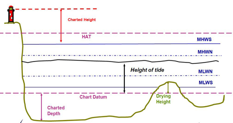
Chart Datum is marked on the diagram below as a purple dotted line and as you can see it is used both:
– for charted depths where the seabed is below Chart Datum;
– and Drying Heights were the seabed is above Chart Datum but that covers at Mean High Water Springs (MHWS).
If you know the height of tide at a given time and location this will be the height above Chart Datum. You can find out more about finding tidal heights on our Tidal Heights page.
Heights on land
Most of the heights of objects on land (above the MHWS line) are measures from MHWS (shown in red on the diagram above).
So for example heights, contours and the height of lights (for example lighthouses) are measures for MHWS.
Clearance under objects
On older charts the clearance under objects is given from MHWS, this is not the case with new charts which refer to Highest Astronomical Tide (HAT), marked in purple on the diagram above.
HAT; the name suggests is the highest the tide would be expected to reach under normal conditions ie. not taking into account air pressure or wind.
You can find the height of HAT above Chart Datum for standard ports on a table of levels on your chart (see example below with HAT in the fourth column).
Links
Check your understanding
Check your knowledge of the basics using this quick self-marking test.
Open the quiz
Progression
If you understand the topics on this page you can now go on to calculate tidal heights.
Feedback
The content of these pages is put together in good faith and is constantly evolving. It is possible that errors exist within this content. If you spot an error or would like to add anything to these pages please contact use via email.
Reading the content of these pages is not a substitute for completing a RYA Shorebased course or similar.
Nautical charts
Projections
Before working with electronic charts (C-MAP, Navionics, BA) it is essential to understand and work with paper charts. Both forms are 2-dimensional representations of a 3-dimensional world which will result in various distortions, yet as long as two requirements are met we can use the 2-dimensional image for navigational purposes:
To fulfil these demands a nautical chart requires parallels and meridians that are both straight and parallel.
Moreover, the meridians will need to be perpendicular to the parallels.
The Mercator chart was designed for sailors and can be constructed by wrapping a cylinder around the planet so that it touches the equator. On this cylinder the surface of the earth is projected and finally the cylinder is cut open to yield the 2-dimensional chart.
However, whereas the meridians converge on the globe they run parallel in the projection (see chart below), indicating the distortion. Subsequently, look at a high parallel: the length / circumference of such a parallel – a small circle – on the globe is much smaller than the equator. Yet, on the chart they have exactly the same length creating a misrepresentation which gets bigger nearer to the poles.
The figure below shows the construction of the Mercator projection. From this it is clear that only the vertical scales should be used for measuring distances.
Click on the world map, above right, to see the distortions of a Mercator projection. Each navy coloured circle / ellipse has a radius of 500 km.

The horizontal scale is only valid for one latitude in the chart and can therefore only be used for the coordinates (a point, but not a line). 
Additional projections
Organization of the chart: Marginalia
Maps have two basic components:
The term marginalia comes from a convention that all additional information about the map was printed / drawn outside the edge of the map, i.e. in the margins. This convention has disappeared with time, but the term lives on.
The most important marginalia that should accompany a map are outlined below:
Information in the chart
Coordinates and positions
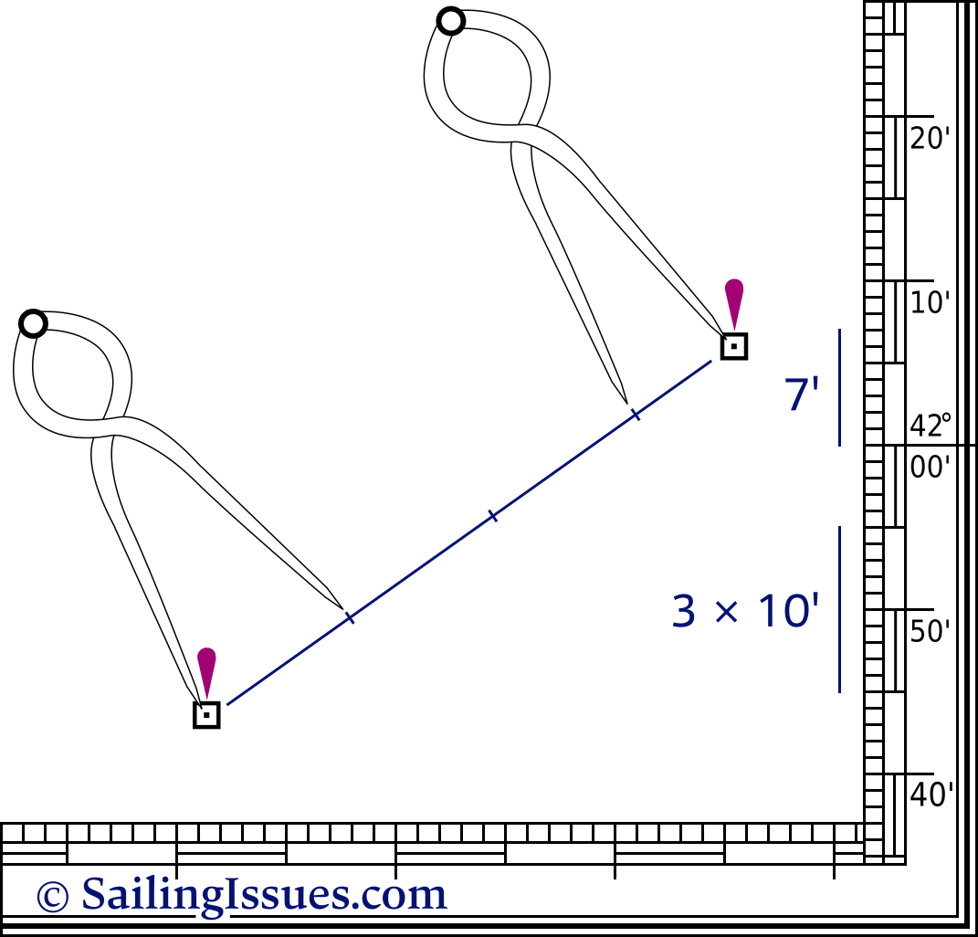
A pair of nautical dividers (single handed dividers) is used to obtain precise coordinates from the chart.
This device enables you to take the distance between that particular position and the closest grid line. You then place the dividers on the scale with one end on this grid line, leaving the other end precisely at your coordinate. Do this twice to get both latitude and longitude at the scale on the edge of the chart.
Below are some examples, excerpt from the PDF :
 | Danger mark 32° 06,3’N 25° 07,3′ E | 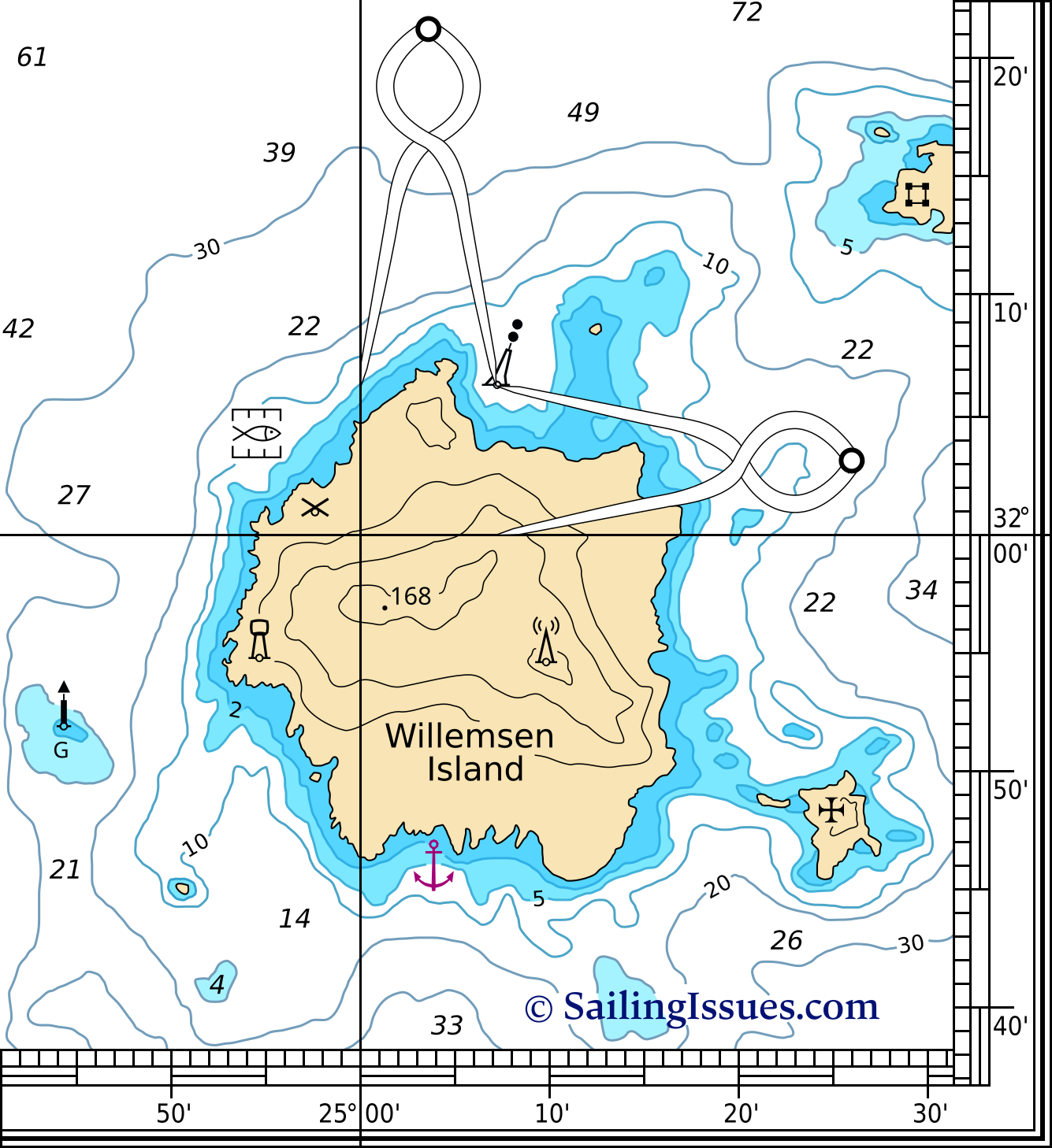 |
 | Fish farm 32° 04,4′ N 24° 54,7′ E | |
 | Anchorage 31° 46,0′ N 25° 04,0′ E | |
 | Church 31° 48,4′ N 25° 25,0′ E | |
 | Windmill 32° 01,0′ N 24° 57,8′ E | |
 | Castle 32° 14,2′ N 25° 29,6′ E | |
 | Water tower 31° 54,9′ N 24° 54,8′ E | |
 | Radio / TV mast 31° 54,8′ N 25° 10,0′ E | |
| Beacon green 31° 52,0′ N 24° 44,3′ E |
Plotting a position in the chart is done by reversing this method.
Some chart symbols come with a line and circle 
Another possible notation of
33° 28,5′ E is
33° 28′ 30″ E, which however doesn’t easily allow for more precision like
33° 28,500′ E does.
Also note that in most countries a comma – and not a period – is used as the decimal separator. Both 33° 28.500′ E and 33° 28,500′ E are valid notations.
Distances
The image shows that the total distance is 37 nautical miles, or 37 NM.
Courses
So, now we can measure distances and both plot and read out positions, but we also need directions. For example we need to find the course from safe-water buoy A to safe-water buoy B. To accomplish this we may use parallel rules as shown in this chart below:
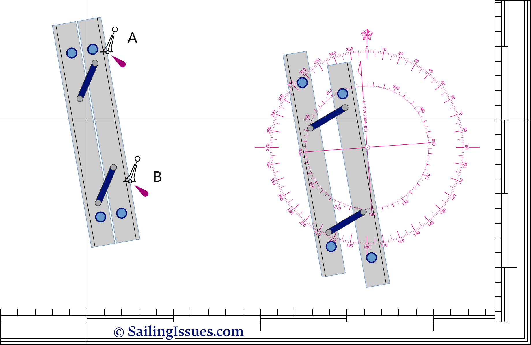 |
First you line this instrument up with the two buoys. Then follows the intriguing part in moving the device to the compass rose without losing its alignment. Finally, when one of the rules is aligned with the heart of the compass card, you can read course A → B. In this example: 170°.
Besides the parallel rules there are other types of instruments available, notably the Breton plotter – also known as a Portland Course Plotter – which features an adjustable rose.
Tides & tidal
prediction
Chart datums
The depths and heights in the chart need a plane of reference: the chart datum (CD).
Depths are usually described with respect to low water reference planes (yielding lower charted depths, which are safer), and heights are shown with respect to high water reference planes (again, yielding lower vertical clearances on the chart, which are safer). As such, the chance that the observed depth or vertical clearance beneath a bridge is smaller than the charted depth or height is rather small. The term clearance height is synonymous with vertical clearance.
Note, planes of reference are not exactly as shown above for all charts. Check for possible notes under the Chart Title.
Charted depths or soundings are indicated on the charts by contour depths (areas with different colour denoting a certain depth level), contour lines and spot depths. These soundings are reduced to the CD, usually Lowest Astronomical Tide (LAT) in tidal waters.
A sounding or spot depth like 35 indicates 3½ metres of water under LAT, whereas an underlined sounding like 04 indicates a height of 40 cm above LAT.
Heights above CD on drying areas are given in metres and decimetres, where the metres figure is underlined.
Depths are given from 0.1 to 20.9 in metres and decimetres, and from 21 to 31 in metres and half metres.
Greater depths are rounded down to the nearest safest metre, e.g. 32.7 metres is rounded down to 32 metres.
The geographical position of a sounding is the centre of the depth figure.
Symbols in the nautical chart for tidal levels and clearances
 | Chart Datum — Datum for sounding reduction |
 | Lowest Astronomical Tide |
 | Highest Astronomical Tide |
 | Mean Low Water |
 | Mean High Water |
 | Mean Sea Level |
 | Mean Low Water Springs |
 | Mean High Water Springs |
 | Mean Low Water Neaps |
 | Mean High Water Neaps |
 | Mean Lower Low Water |
 | Mean Higher High Water |
 | Mean Higher Low Water |
 | Mean Lower High Water |
 | Power lines  Vertical clearance indicated between  Pylons emphasised with  |
 | Power lines with safety vertical clearance indicated between magenta  |
 | Overhead pipes with vertical clearance |
 | Aerial cableway with vertical clearance |
 | Telephone lines with vertical clearance |
 | Fixed bridge with vertical clearance Horizontal clearance is charted with  |
 | Opening bridge with vertical clearance |
 | Offshore position for which tidal levels are tabulated Magenta square and lower case lettering |
Currents and tidal streams
Symbols in the nautical chart for currents and tidal streams
 | Flood tidal stream with rate |
 | Ebb tidal stream with rate, no feathers |
 | Relatively constant current (in restricted waters), non-tidal |
Variable current (in restricted waters), non-tidal

Tide rips
Races


Position of tabulated tidal stream data with designation
Magenta rhombus and upper case lettering


 to avoid obscuring the shoal soundings or feature.
 Ocean current.
 Details of current strength and seasonal variations may be shown:
Tidal levels in the chart

Levels are included in the same chart and tabulated in a tidal level table, such as the three examples below.
There are different table variations for semi-diurnal, mixed semi-diurnal and diurnal tides.

Note, that the coordinates don’t give the leading zeros, especially the longitude positions, e.g. 2° W instead of 002° W. This to safe space and reduce chart clutter, also see the style guide.
Tidal streams in the chart


Note, that “Dir” is direction towards as opposed to wind directions! Furthermore, “Np” stands for Neap tide and “Sp” for Spring tide.
The direction or set is given in degrees. The rates or speeds for spring and neap tides are given in knots.
Eastbourne in this example serves as a reference port. At high water at Eastbourne and the hours before and after HW Eastbourne, the rates and sets are tabulated for the locations of these three chart diamonds.
Tidal diamonds give the tidal streams at that location only, a nearby diamond may yield very different sets and rates; sensible interpretation and comparison may be used to estimate the streams at intermediate positions.
Tidal atlases
An atlas is a collection of maps or charts, and is named after the Ancient Greek mythological figure Ἄτλας “Bearer (of the Heavens)”, and a tidal atlas presents tidal stream information in the form of 12 or 13 chartlets, one for each hour of the tidal cycle.
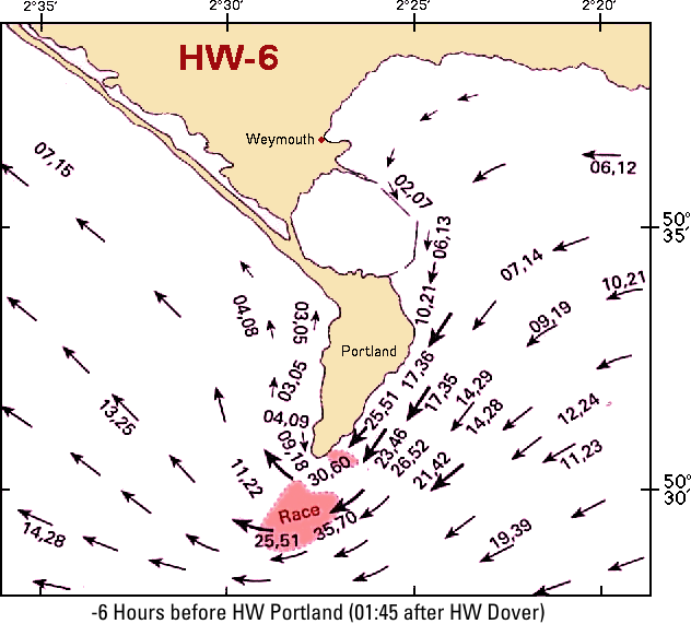
Above is an example of one chartlet, part of a set of 12, featuring Portland Bill (South England) 6 hours before HW Portland.
Both types of presentation use relative times with respect to HW at a particular port, instead of clocktime.
Tide tables
Tidal levels featured in the chart only give heights of tides, not times. Annual tide table books are used on board which specify the times of each HW and LW for each day of the year for standard ports (larger ports or reference ports). These publications should be used alongside the online tide resources (UK, USA, FR, NZL …)
There are many tide table variations across countries and some mention times for high water only (view Cherbourg). More often the lunar phases 🌑 🌒 🌓 🌔 🌕 🌖 🌗 🌘 🌒, or neap and spring tides, or time difference between the two are added (i.e. Spring tide occurs two days after full and new moon.). Furthermore, dates to with daylight saving time applies can be conveniently indicated (view Dover).
The image below shows a portion of a typical tide table for any standard port. Note, that in (mixed) semi-diurnal tides, the tidal period is 12 hours and 25 minutes: from high tide to the next high tide. Therefore there are days, like Wednesday 2 January in this example, with just three entries.
Times, time zones, UTC, GMT and Z
Times, in meteorology as well as nautical publications, are given using the 24-hour clock, based on the standard time of the country concerned. When a daylight-saving scheme is in operation, an hour has to be added to the time shown in the tide table or weather forecast in order to convert it to clock time.
The UK uses GMT (Greenwich Mean Time) and BST (British Summer Time in the summer months) as local time, but for instance France, Belgium and the Netherlands are one hour ahead, since located in the adjacent time zone; UTC+1. In order to convert a French tide table into GMT substract one hour. Most yachtsmen prefer to work in local time, rather than referring back to a home port’s time zone.
GMT, CET (Central European Time; UTC+1) or for instance EST (Eastern Standard Time in the USA, New York; UTC-5) are time zones and based on the rotation of the earth.
UTC (Coordinated Universal Time) = Z (Zulu time) is not a time zone, rather is based on the caesium atomic clock.
For navigational purposes both UTC and GMT (though now obsolete outside the UK) are regarded as interchangeable, yet UTC is recognized globally and the time zone offset should always be written as UTC±00.
Times should be written as 01:10 and not as 0110
Likewise, time differences as ±01:10 instead of ±0110
Notations with a colon (:) will also emphasize the correct meaning of 1 hour and 10 minutes (70 minutes) and not 110 minutes.
Tidal curves
Tide tables give the heights for HW and LW each day, but to calculate the heights of tide between high and low waters, the standard ports have associated tidal curves published. It is far more likely that intermediate heights and times are required when entering/leaving a harbour, especially if there is a bar or sill (cill) to cross.
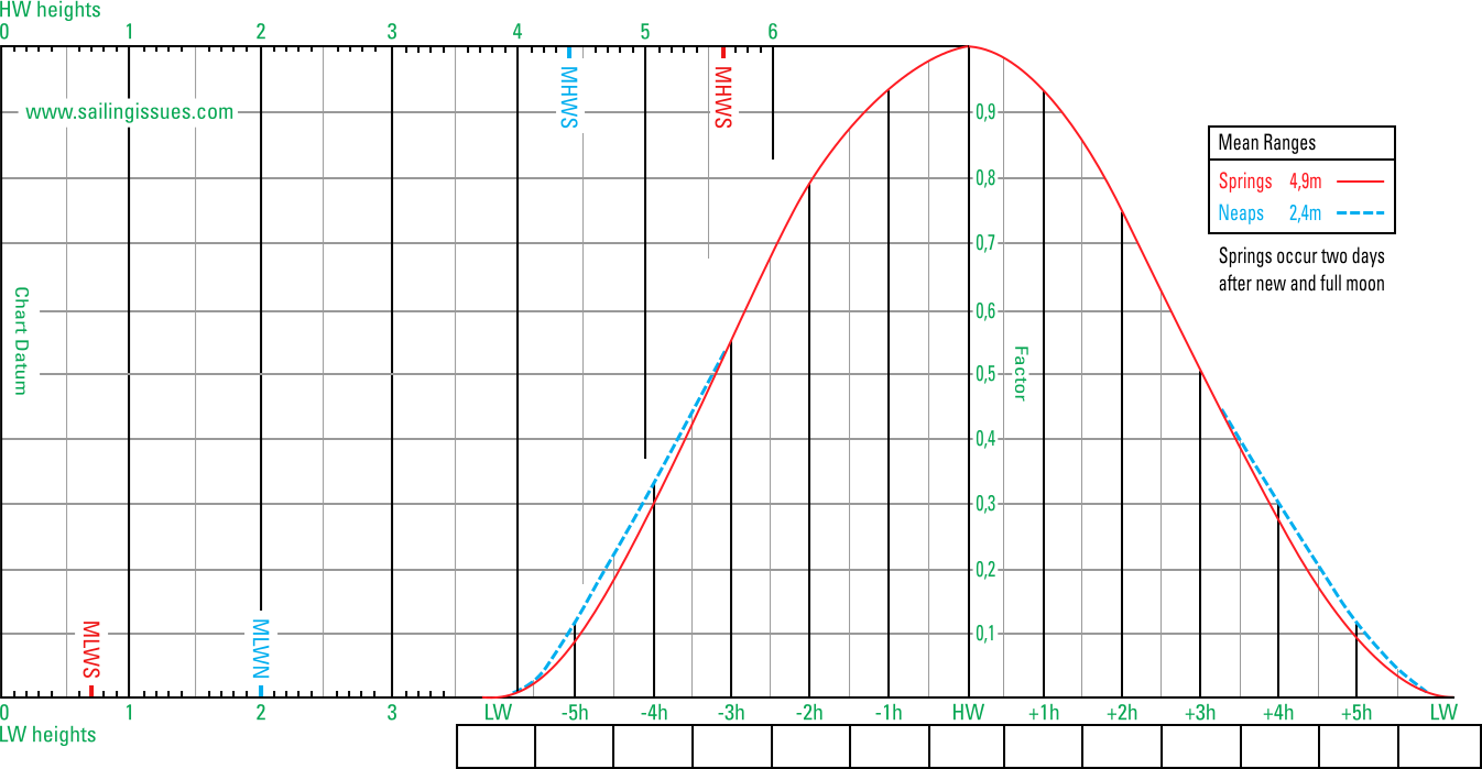
The image below shows a typical tidal curve for a standard port with both spring tide and neap tide drawn. Here the mean range at spring tide is 4,9 m and and neap tide is 2,4 m.
Using the tidal curve to find height of tide

Using the added times after HW, plot the time of 15:50 on the horizontal axis of the curve.

End drawing the vertical line where it intersects with the red spring tide curve. Often the neap tide curve (dotted line) has a different shape.

End drawing the horizontal line where it intersects with the drawn diagonal.

From the intersection draw a vertical line (upwards is handier) and find the requested height of tide: 3,5 metres that corresponds with 15:50.
This answer can be verified using by the factor scale show above HW: 0,8 (start point of the range) + 0,56 (factor) * 4,9 (range) = 3,5 height of tide.
Using the tidal curve to find times

Start from HW and work towards both LWs.

Start this line at the top scale at 2 m and end drawing where it intersects the diagonal.

This horizontal line will intersect red spring tide curve twice.

One of these lines meets the time scale on the left side of HW, the other on the right side of HW.

In this example the height of tide will be 2 m at 08:52 and at 17:05. Between these times the height of tide will be larger.
Secondary ports
Many of the more picturesque harbours and attractive anchorages visited by yachtsmen are classified as secondary ports. Since these smaller ports are of less commercial or military importance than standard ports neither tidal curves nor full tide tables are available.
Fortunately, often the differences with a nearby standard port are tabulated by which it is possible to use standard port tidal information to yield predictions for a secondary port.
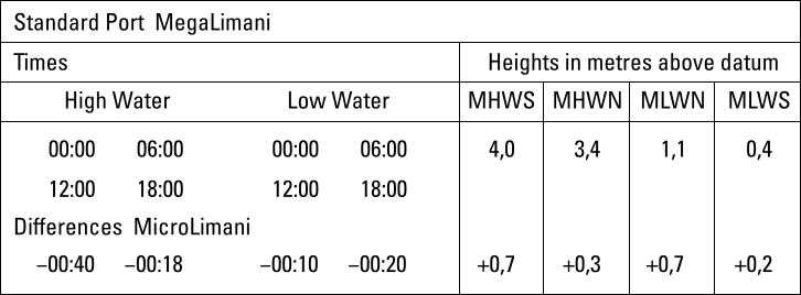
The image above shows the tidal difference table for MicroLimani (i.e. “small port” in Greek) as the secondary port and MegaLimani as standard port.
Time of HW at MicroLimani by interpolating
Instead of the calculations, there is a second interpolation method by means of drawing a graph as below. Start by marking the two blue axes: horizontally the time differences; and the angled axis with the times (or vice versa). Then mark the time 14:04 along the time axis. Finally, draw the small red line perpendicular to the larger red line.
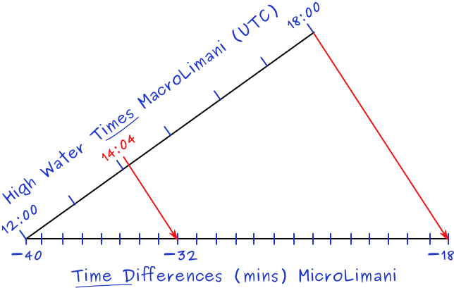
In case of daylight saving time the last step would be to add 1 hour.
Rule of twelfths
Tidal curves are usually only available for standard ports where most sailing yachts would have ample water anyway; not in out of the way anchorages and smaller ports.
So how to determine the height of the tide that is available to safely approach a depth restricted anchorage, harbour or pass over a sand bar?
Rule of seven
To interpolate between spring and neap tides we use the rule of seven.
Combining tidal predictions
1. Shoal problem
A standard navigational problem is to establish whether the height of tide allows the crossing of a shoal, or, if not, the time at which the tide will have risen sufficiently.
The shoal at Dowes has a charted depth of 1 meter, which needs to be crossed at about 15:00 hours with a yacht with a draft of 2 m.
From the nautical almanac: Nearest standard port HW at 03:18 15:53 and LW occurs at 09:45 22:03
HW occurs at Dowes one hour later = 16:53.
Clearance under the keel in calm weather and no waves or swell should be 0.5 m minimum. Good practice however is to have at least a clearance of 1 meter + wave or swell height.
2. Bridge problem
An example:
Above our shoal hangs the ‘Cowes bridge’. At 15:00 hours we would like to pass this bridge, which has a charted height of 20 meters to HW. Our mast is 23 meters high. In the example above we found that the water height was 1,1 meters below HW level at that time. Obviously, we will have to wait!
So, at what time will we be able to pass under this bridge?
The water height must be 3 meters lower than HW level (5,0 m). That is almost 9/12 of the range (4,3 m) indicating four hours after HW 
Weather influences on tides
For standard ports, shipping lanes, etc. these predictions are published on nautical charts, in tidal atlases and tide tables.
Yet, local wind and weather patterns will also affect tides and are obviously not taken into account in these publications.
Strong offshore winds can move water away from coastlines, exaggerating low tide exposures. Onshore winds may act to pile up water onto the shoreline, sometimes even eliminating low tide exposures. A prolonged force 5 blowing onshore (a temporary wind-induced current) can raise the sea level by 2 decimetres.
High-pressure systems can depress sea levels, leading to clear sunny days with exceptionally low tides. Conversely, low-pressure systems that contribute to cloudy, rainy conditions typically are associated with tides than are much higher than predicted. Every extra 11 mbar of pressure (Greek: βάρος baros, meaning “weight”) can affect a change of 1 decimetre.
The combined effect of wind and barometric pressure typically produces variations of roughly ± 2 decimetres in height and ± 10 minutes in time, yet with extreme northerlies blowing down into the funnel-shaped North Sea, for instance, a raise of 2 metres and with a storm tide even 5 metres is possible.
Although tidal calculations should be carried out as meticulously as possible, their accuracy should not be relied on. Furthermore, even a small distance away from the actual position of tabulated tidal data could mean significant differences in times and tidal heights, set and rate.
Tidal streams and sea state
The wave conditions or sea state can be influenced by either tidal streams or winds, or by a combination of winds and tidal streams.

Overview


The Internet Content Rating Association has labelled and checked the content of this website.


